Hydrogen oxygen generation system for an internal combustion engine

a technology of hydrogen oxygen and internal combustion engine, which is applied in the direction of transportation hydrogen technology, machines/engines, mechanical equipment, etc., can solve the problems of loss of efficiency, inadequate efficiency and economic returns, and limitations of all

Inactive Publication Date: 2006-05-04
EHRETEK
View PDF8 Cites 45 Cited by
  • Summary
  • Abstract
  • Description
  • Claims
  • Application Information

AI Technical Summary

Benefits of technology

[0010] Because of the recombining effect that occurs at the anode, electrolysis alone does not produce enough hydrogen to economically power an

Problems solved by technology

Although each device has its merits, all have limitations based upon the high amount of energy required to chemically split pure water into its basic subcomponents to create gaseous hydrogen (H2) and oxygen (O2).
Known apparatus and methods require either a device that is too large for practical use in personal travel vehicles such as cars, trucks, small planes, and motorcycles, or a device that provides inadequate efficiency and economic returns to offset the costs associated with implementing the devices in motor vehicles.
Electrolysis-associated issues include a loss of efficiency due to the generation of undesirable contaminants and reaction by products such as sediment from electrolytes, as well as decomposition and eventual destruction of the anode components due to oxidation and corrosion.
The use of acetic acids and precious metals in known systems helps to mitigate the corrosive nature of electrolysis and its generated by-products, but also creates new problems with respect to safety, environmental concerns, as well as economic concerns of cost, thus making known devices impr

Method used


Image

  • Hydrogen oxygen generation system for an internal combustion engine
  • Hydrogen oxygen generation system for an internal combustion engine
  • Hydrogen oxygen generation system for an internal combustion engine

Examples


Embodiment Construction

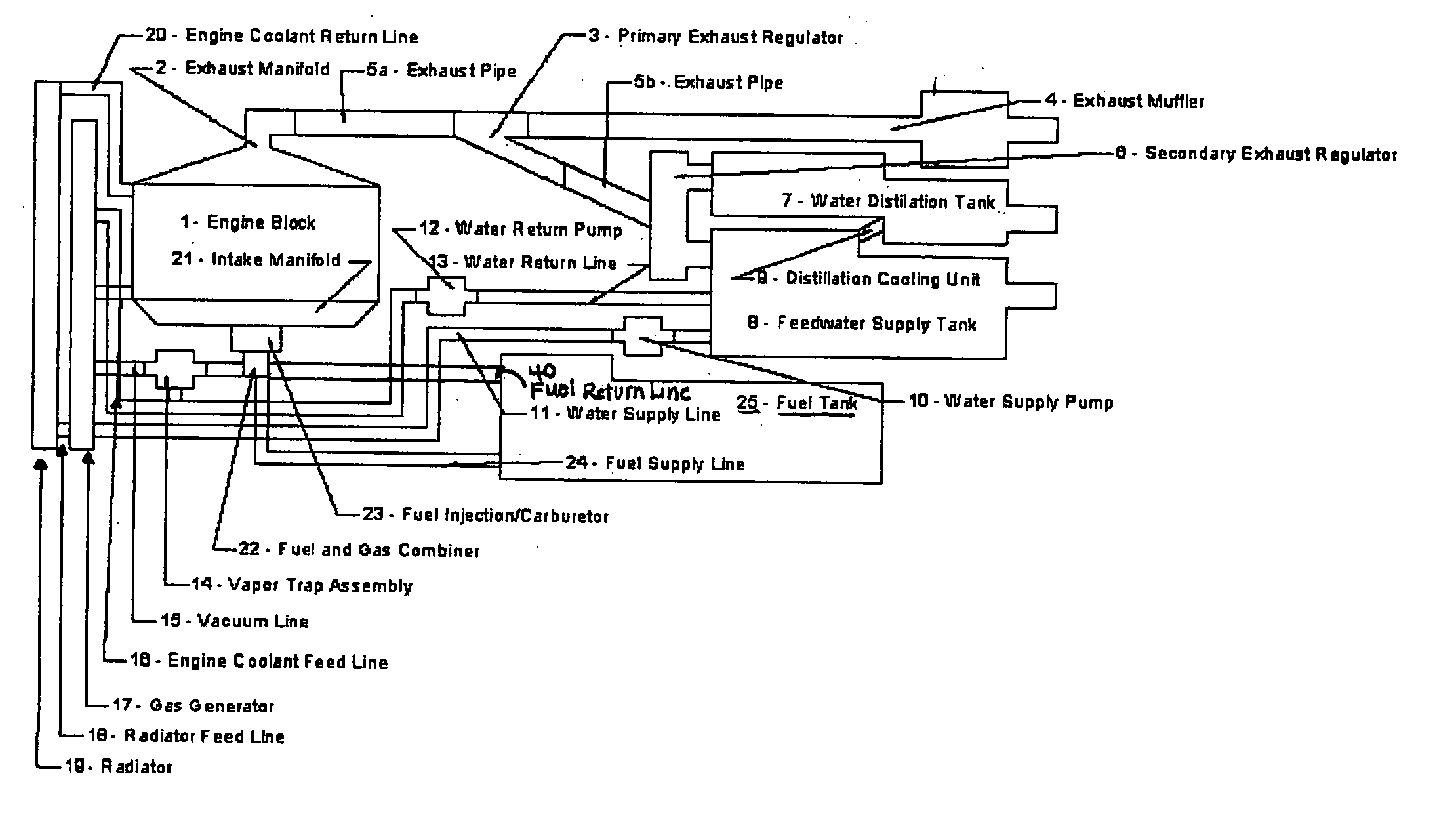
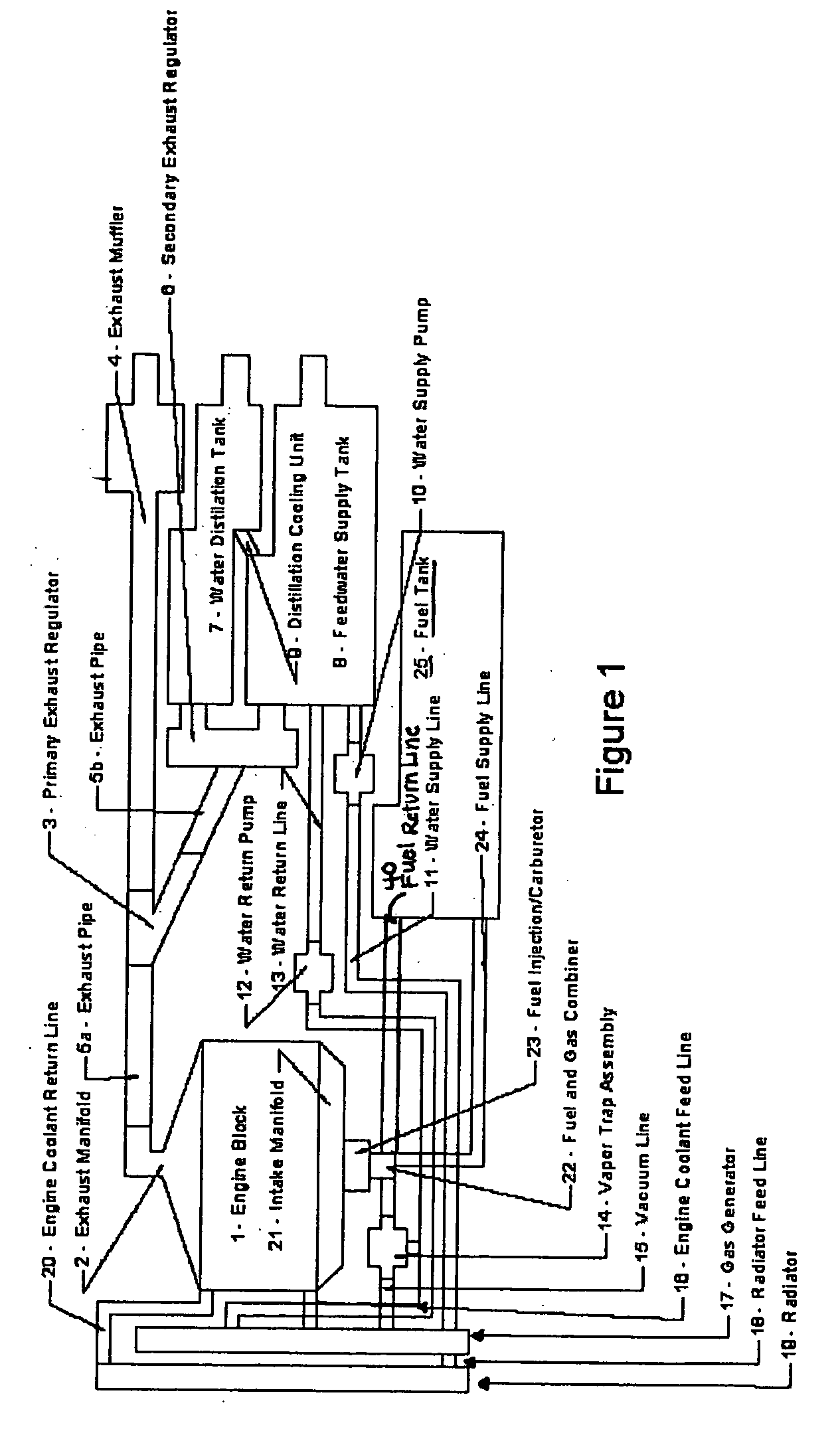
[0018] Every internal combustion engine generates heat energy as a by-product that is lost to the environment. The heat loss occurs in three primary ways; via inherent or forced air cooling, heat exchange from the engine block via cooling jacket water, and the loss of heat through the exhaust manifold and exhaust system. The present invention uses ambient, inductive and conductive thermal transfer processes to capture the internal combustion engine's generated heat. The captured heat is used to heat water, and the heated water is then subjected to electrolysis to generate hydrogen and oxygen gases in a quantity sufficient to either supplement an internal combustion engines existing fuel source, or to act as the sole fuel source, such as in a lightly loaded combustion engine environment. As generally illustrated in FIGS. 1-3, this invention uses an internal combustion engine's cooling jacket water, exhaust gases and radiant engine heat in order to heat (such as inducing a boiling sta...


PUM


Abstract

A system is provided which, when integrated with an internal combustion engine, generates hydrogen and oxygen gases to enrich an internal combustion engine's petroleum fuel source. The system's primary components are a gas generation unit, heated water supply tanks, and a gas combiner for mixing generated hydrogen and oxygen gas with petroleum fuel to create hydrogenated and oxygenated petroleum fuel. The gas generation unit includes at least one cathode, at least one anode, vacuum regulatory units, a thermal transfer system, an electrical heating element, a feedwater management system, a gas collection and supply system, and water traps. The heated water tanks include a thermal transfer system, pressure and regulatory units as well as a distillation apparatus for producing distilled water. Electrical power is supplied to the system's power amplifier from the internal combustion engine's alternator or associated electrical system.

Description

FIELD OF THE INVENTION [0001] The present invention relates to internal combustion engines, and particularly to fuel supply systems for internal combustion engines. A system is provided which, when integrated with an internal combustion engine, generates hydrogen and oxygen gases to supplement an existing fuel source, and / or to serve as the engine's sole source of fuel. The system's primary components include a gas generation unit, at least one heated water supply tank, and a gas combiner. BACKGROUND OF THE INVENTION [0002] Water is one of the most abundant liquids on earth. As a highly stable liquid, all forms of life known to man depend on it for survival. For centuries man has dreamed of splitting this readily available liquid into its base components—hydrogen and oxygen in order to create a cheap, renewable, clean burning power source. [0003] Several device designs exist that use electrolysis to generate hydrogen and oxygen to either replace or supplement fuels burned in interna...

Claims


Application Information

Patent Timeline
IPC IPC(8): F02B43/10F02M25/00
CPCF02B43/10F02M25/12Y02T90/42Y02T10/32Y10S123/12Y02T10/121Y02T10/12Y02T10/30Y02T90/40
Inventor EHRESMAN, KENNETH L.
Owner EHRETEK
Why Eureka
Try Eureka