Pressure control system in a photovoltaic substrate deposition apparatus

a technology of pressure control system and photovoltaic substrate, which is applied in the direction of sustainable manufacturing/processing, final product manufacturing, vacuum evaporation coating, etc., can solve the problems of insufficient reduction of product cost, difficult expansion of process to a commercial scale, and efficient thin-film manufacturing process

Inactive Publication Date: 2006-05-11
DAYSTAR TECHNOLOGIES
View PDF36 Cites 94 Cited by
  • Summary
  • Abstract
  • Description
  • Claims
  • Application Information

AI Technical Summary

Benefits of technology

[0015] This invention further comprises a method for pressure control in a plurality of independent deposition and reaction chambers comprising controlling the influx of a gas into the reaction chambers, feeding a substrate through orifices at the inlet and outlet of the reaction chambers, establishing an isolation zone of lower pressure adjacent to and in communication with the reaction chambers and removing the gas exiting the reaction chamber to prevent cross contamination into an adjacent reaction chamber.
[0016] The advantage of this apparatus is the isolation of the reaction chambers to prevent cross contamination while, at the same time, it allows a substrate to pass uninterrupted from one chamber to another. In one embodiment, a pallet or number of pallets may exit one reaction chamber and be temporary situated in an isolation zone while minimizing adverse effects to the substrate and then enter the next subsequent reaction chamber at some later time. In another embodiment, the pallets may be organized in a train like fashion such that all reaction chambers are operational simultaneously on different pallets. This invention also makes possible a continuous, or “roll-to-roll”, substrate design moving continuously through a series of reaction chambers, each separated by a pressure controlled isolation zone. Although many references disclose the concept of a continuous substrate, the current invention enables the photovoltaic manufacturing process to be truly continuous.
[0019] Another object of this invention enables the transfer a substrate from one reaction chamber to the next subsequent chamber, or to the outside atmosphere, without subjecting the substrate to large temperature and pressure changes during the transfer.
[0020] A third object of the present invention is to transfer a substrate from a reaction chamber to the next subsequent reaction chamber without allowing cross contamination between the two reaction chambers.

Problems solved by technology

Unfortunately, product costs have not been sufficiently reduced to open up the critical markets in the developing world where electricity demand is driving them to polluting, non-renewable sources such as coal and oil.
However, although relatively efficient PV cells can be manufactured in the laboratory, it has proven difficult to enlarge the process to a commercial scale with consistent repeatability and efficiency critical for commercial viability.
The lack of an efficient thin-film manufacturing process has contributed to the failure of PV cells to effectively replace alternate energy sources in the market.
Currently, cells are manufactured using a multi-step batch process wherein each product piece is transferred between reaction steps and such transfer is bulky and requires reaction in chambers to be cycled.
One drawback to this process is that the substrate is transferred from vacuum to air and back to vacuum several times. An alternate system uses a series of individual batch processing chambers coupled with a roll-to-roll continuous process for each chamber.
The major drawback in this process is the discontinuity of the system and the need to break vacuum.
Also, while enabling the substrate to travel between two reaction chambers, the apparatus must not allow reactants in one reaction chamber to contaminate another reaction chamber.
However, this patent does not contemplate the use of a pure gas in concert with a differential pumping arrangement to control the pressure in a reaction chamber.
Nor does Coleman teach a continuous manufacturing process.

Method used


Image

  • Pressure control system in a photovoltaic substrate deposition apparatus
  • Pressure control system in a photovoltaic substrate deposition apparatus
  • Pressure control system in a photovoltaic substrate deposition apparatus

Examples


Embodiment Construction

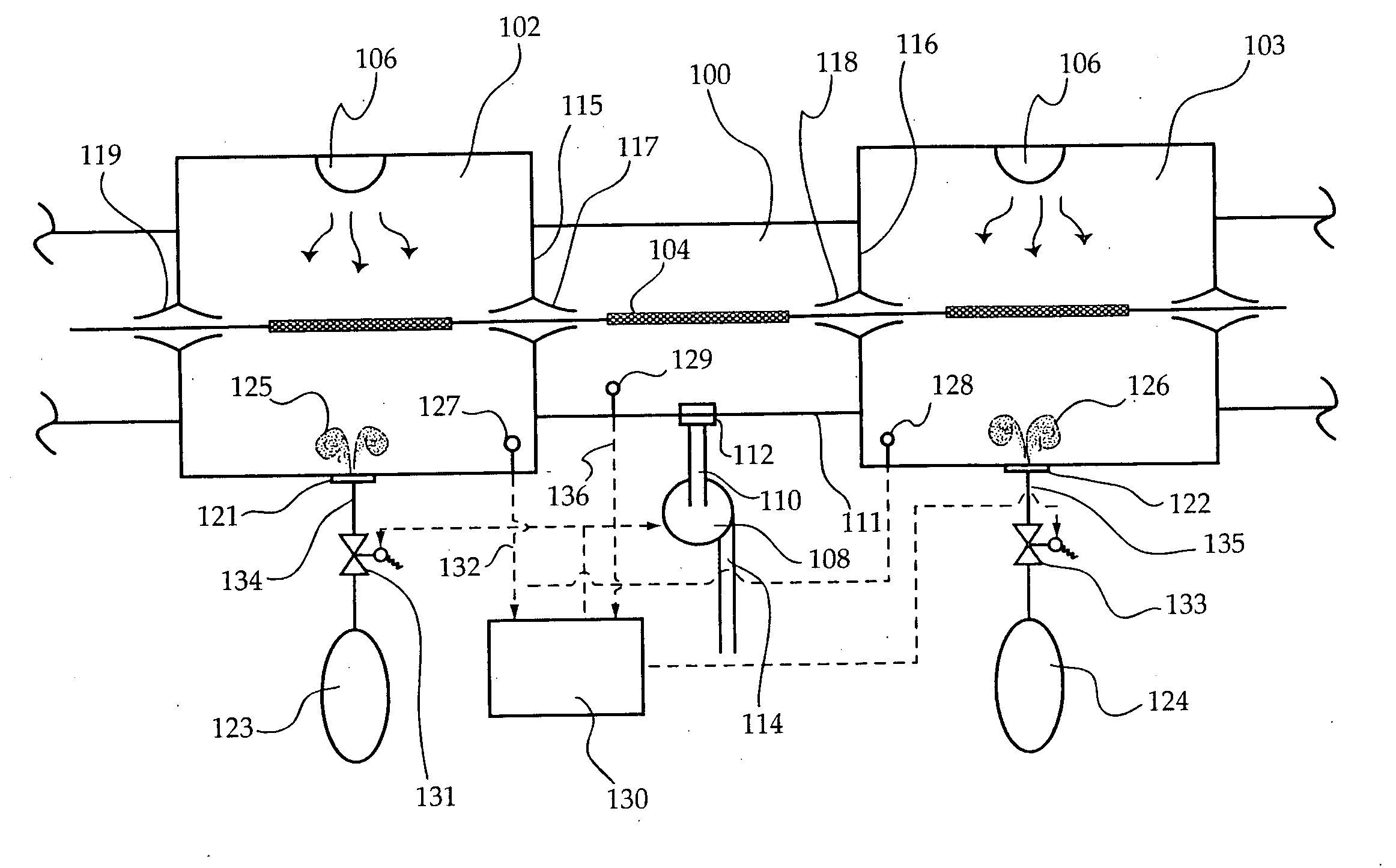
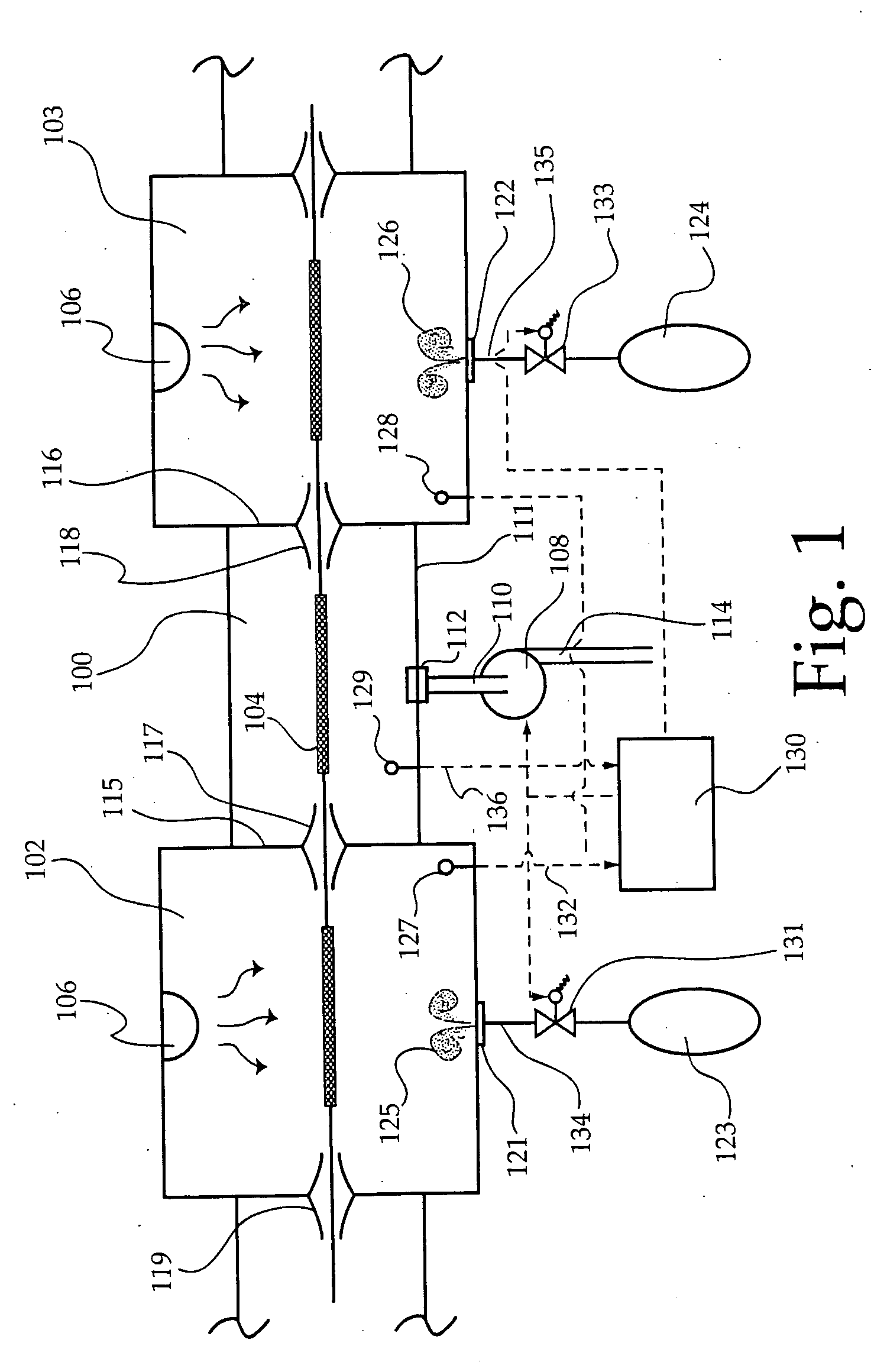
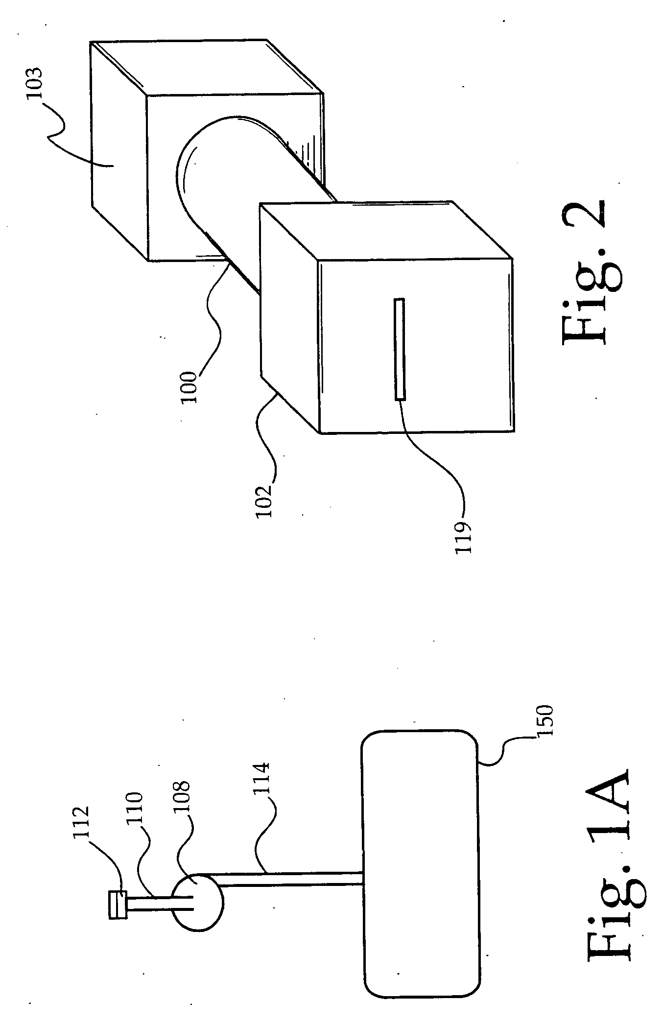
[0028] An embodiment of the current invention is depicted in FIG. 1 and comprises an enclosed isolation zone 100 that is attached to at least one reaction chamber 102 but, in most cases, the enclosed isolation zone 100 is attached between two reaction chambers 102. The physical shape of the isolation zone 100 may be any shape, such as cube or rectangular, and may be determined by the size of the pallet, work piece, or other substrate transportation device 104. Obviously, the shape of the isolation zone 100 may be driven by optimizing performance in a vacuum, therefore a cylindrical, as depicted in FIG. 2, or spherical shape may be necessary to support drawing a vacuum in the area of 10−7 torr. The size of the enclosed isolation zone 100 may also be determined by the reaction requirements of the photovoltaic production process. Factors which may influence the length of the isolation zone 100, for example, may be issues such as internal pressure of adjacent reaction chambers, residenc...


PUM

PropertyMeasurementUnit
pressureaaaaaaaaaa
pressuresaaaaaaaaaa
pressureaaaaaaaaaa

Abstract

This invention comprises an apparatus for the deposition of thin layers upon a substrate for the production of photovoltaic cells wherein the individual reaction chambers are separated from each other by low pressure isolation zones which prevent cross contamination of adjacent reaction chambers and control pressure levels in each reaction chamber while, at the same time, allowing the uninterrupted transfer of a substrate from one reaction chamber to the next without any mechanical obstruction.

Description

CROSS-REFERENCE TO RELATED APPLICATIONS [0001] This application claims priority from U.S. Provisional Patent Application Ser. No. 60 / 626,843, filed Nov. 10, 2004.FIELD OF THE INVENTION [0002] This invention relates to the production of photovoltaic cells and more specifically to a pressure control and isolation system for the uninterrupted transfer of a photovoltaic work piece from one reaction chamber to another. BACKGROUND OF THE INVENTION [0003] Photovoltaic (PV) cells, modules and power systems offer clean, reliable, renewable energy to the World's expanding demand for electrical power. Unfortunately, product costs have not been sufficiently reduced to open up the critical markets in the developing world where electricity demand is driving them to polluting, non-renewable sources such as coal and oil. With the population expanding, and per-capita energy consumption going up, the world is heading towards an irreconcilable future where energy demand and supply irreversibly diverge...

Claims


Application Information

Patent Timeline
Patent Type & Authority Applications(United States)
IPC IPC(8): C23C16/00
CPCC23C14/562C23C14/568H01L31/206Y02E10/50Y02P70/50
Inventor TUTTLE, JOHN R.
Owner DAYSTAR TECHNOLOGIES
Why Eureka
Try Eureka