Fertilizer injector wing for disc openers

a technology of fertilizer injector and disc opener, which is applied in the direction of climate sustainability, potato planters, agriculture gas emission reduction, etc., can solve the problems of reducing the effectiveness of fertilizer available, affecting the use of fertilizer, and affecting the effect of fertilizer release, etc., to achieve the effect of reducing weed growth and moisture loss, reducing disturbance, and high speed us

Inactive Publication Date: 2006-05-18
EXACTRIX
View PDF2 Cites 76 Cited by
  • Summary
  • Abstract
  • Description
  • Claims
  • Application Information

AI Technical Summary

Benefits of technology

[0009] The present invention provides a unique fertilizer injector wing that affixes to a seed boot of a low disturbance disc opener that enables an improved method of placing a seed row with a dedicated band of fertilizer at an optimum geometric positional alignment relative to the seed row. The inventive wing and method of use enables a toxic charge of fertilizer (e.g., a charge containing the entire nutrient package to sustain season long growth) to be placed in close proximity

Problems solved by technology

While no-till farming greatly reduces the escape of CO2 by reducing the mineralization of the organic matter in the soil, it also undesirably prevents the release of organic nitrogen into the soil, which is needed by the new seedlings in order to grow.
These prior art no-till fertilizing methods are problematic and subject to several limitations.
For example, with both mid-row banding and paired row banding, each fertilizer row must be shared by at least two seed rows thereby reducing the effectiveness of the fertilizer available to any one row and thus undesirably diminishing the yield.
Mid-row banding is further problematic in that the fertilizer must be remotely placed from the seed rows thereby undesirably allowing weeds exposed along the fertilizer furrow better access to the band than the remote seed rows.
This additional cutting equipment is

Method used


Image

  • Fertilizer injector wing for disc openers
  • Fertilizer injector wing for disc openers
  • Fertilizer injector wing for disc openers

Examples


Embodiment Construction

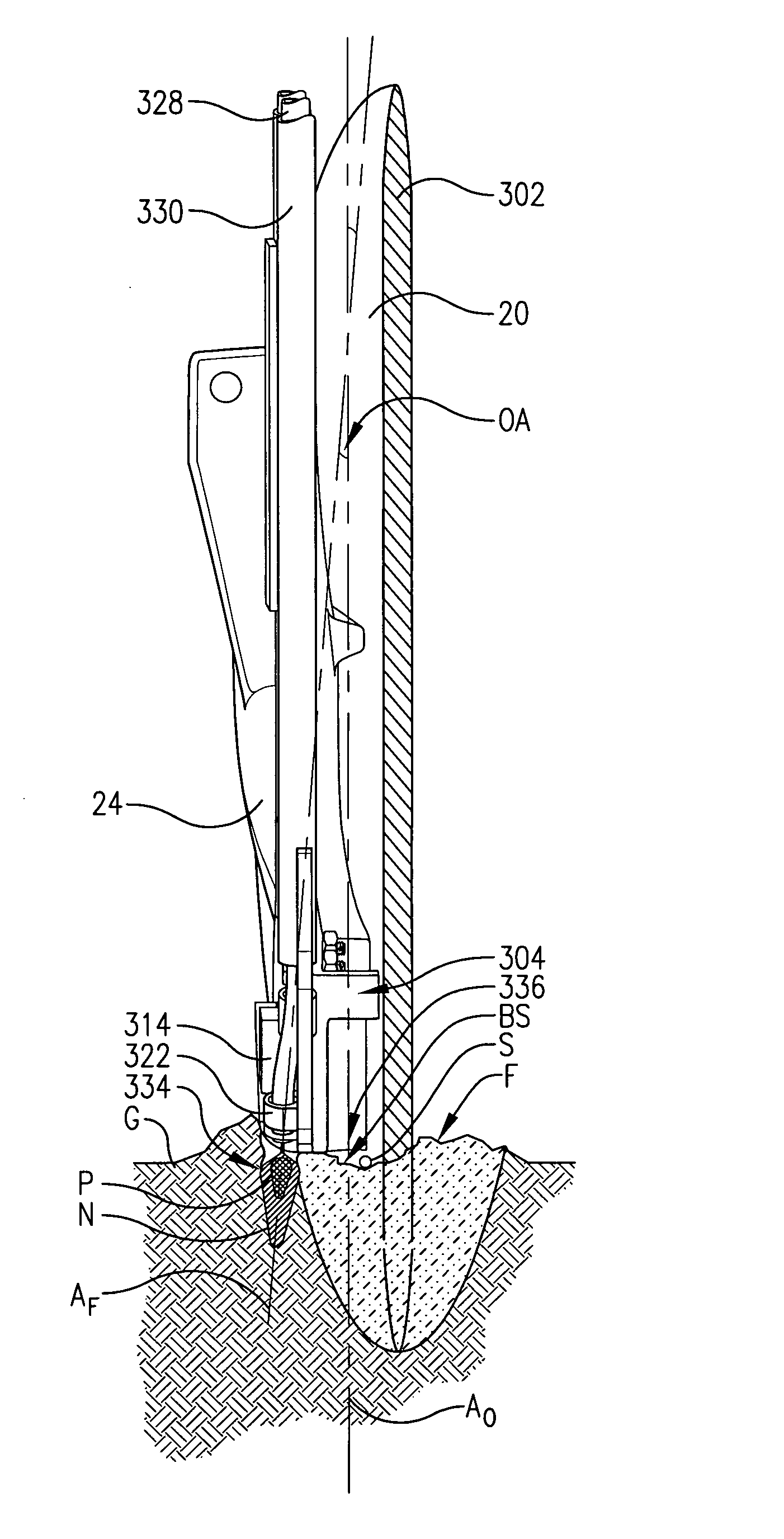
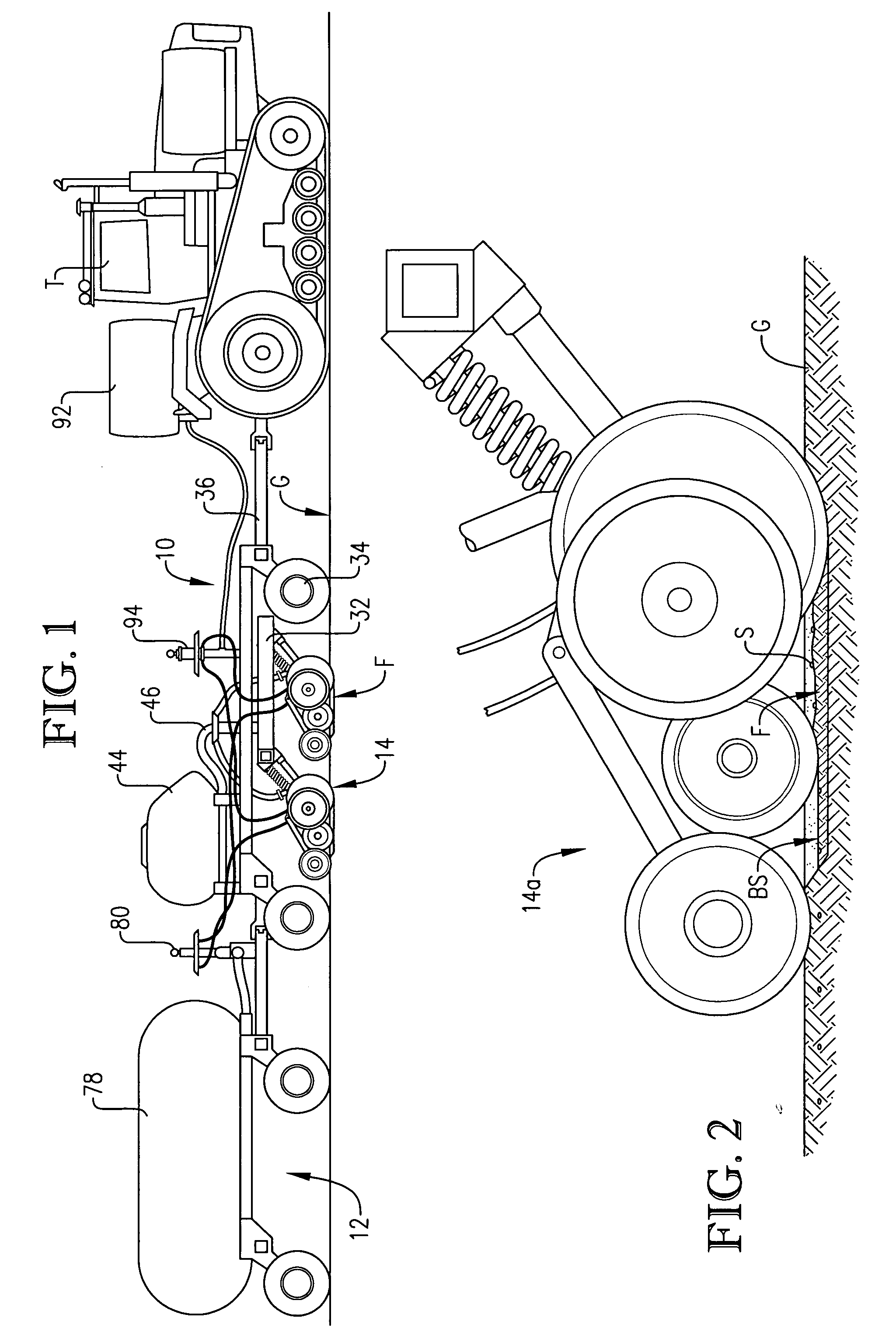
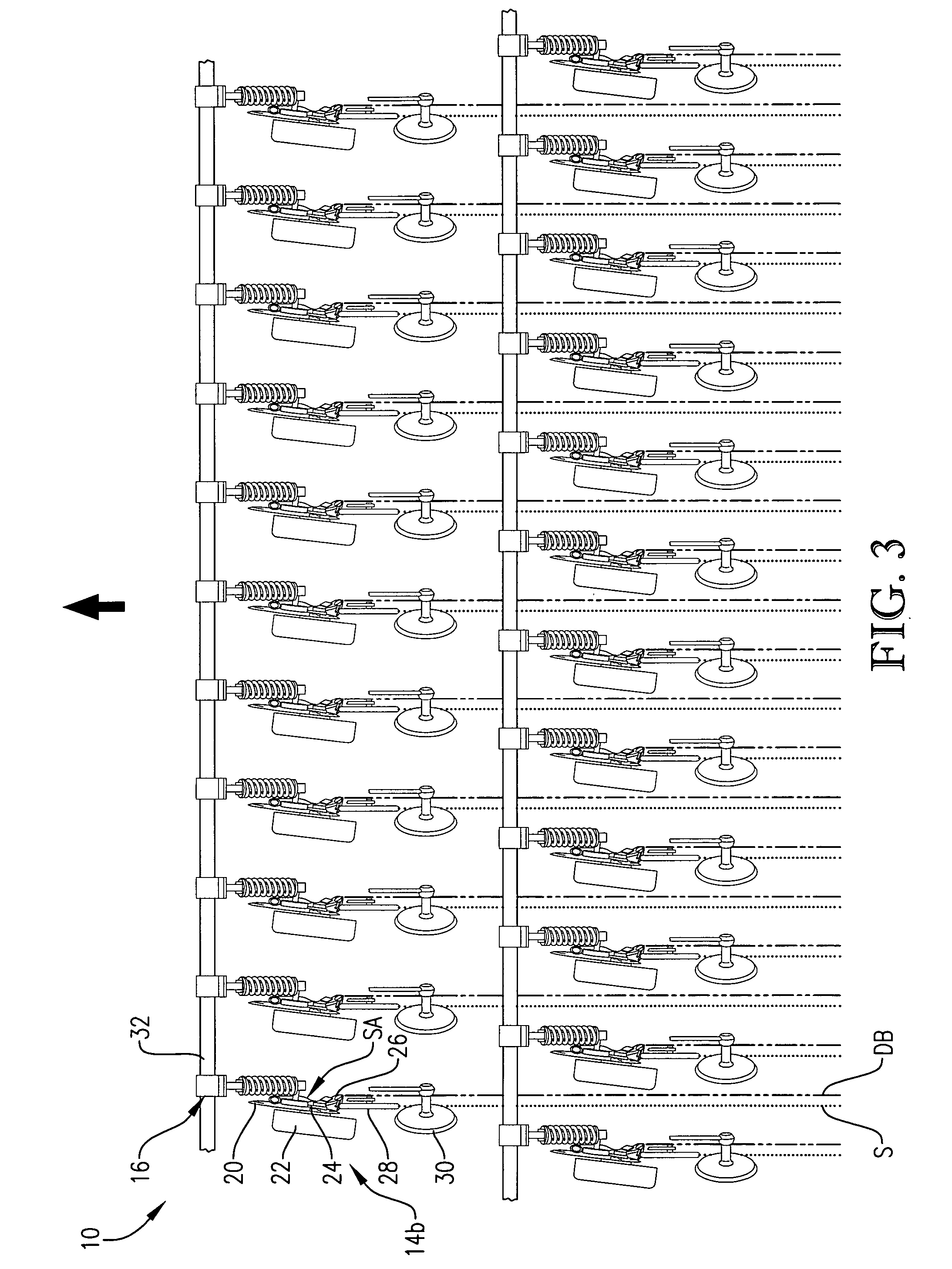
[0036]FIG. 1 illustrates a tractor T pulling an air seeder 10 and a tow-behind fertilizer cart 12 configured for seeding and fertilizing a field G for crop production. The seeder 10 includes a plurality of single disc openers 14 constructed in accordance with the principles of a preferred embodiment of the present invention, with representative right and left disc openers 14a and 14b, respectively, being illustrated in detail in FIGS. 2-11. While the principles of the present invention are particularly well suited for low disturbance, no-tillage single disc applications, these principles could be readily applied to virtually any seeding and / or fertilizer application in which a furrow is opened for in-ground placement of the seed and / or fertilizer. Furthermore, the principles of the present invention are not limited to the production of any particular crop and can readily be adapted to virtually all crops generated by in-ground placement of seed and / or fertilizer. The illustrated ope...


PUM


Abstract

Disc openers (14) for use with an air seeder (10) are configured for seeding and fertilizing a field (G). The opener (14b) broadly includes a coulter disc (20), a seed boot (24), and a fertilizer injector wing (26). The fertilizer injector wing (26) is configured for fixed attachment to the seed boot (24) and broadly includes a body (48), including an angled outboard portion (56), a toxic fertilizer injector (50), and a non-toxic fertilizer injector (52). The opener (14b) with the fertilizer injector wing (26) is configured to place the seed row (S) and the dedicated fertilizer band (DB) at an optimum geometric positional alignment relative to the seed row (S), in a single, low soil disturbing planting pass without disrupting the seed bed (BS). In alternative wings (300 and 400), the sufficiently safe geometric positioning is accomplished by the force of delivery of the fertilizers (N and P) coupled with an offset angle (OA) defined between a fertilizer injection axis (AF) and a seed outlet axis (AO).

Description

RELATED APPLICATIONS [0001] This application is a continuation-in-part of application Ser. No. 10 / 659,564, filed Sep. 9, 2003, which is hereby incorporated by reference herein.BACKGROUND OF THE INVENTION [0002] 1. Field of the Invention [0003] The present invention relates generally to a method and apparatus for placement of fertilizer and seed during planting of an agricultural crop. More specifically, the present invention concerns a fertilizer injector wing that affixes to a seed boot of a low disturbance disc opener and a method of using the winged opener to place a seed row and a dedicated band of fertilizer at an optimum geometric positional alignment relative to the seed row. The inventive wing and method of use enables a toxic charge of fertilizer (e.g., a charge containing the entire nutrient package to sustain season long growth) to be placed in close proximity with the seed row in a single, relatively high speed, low soil disturbing planting pass of relatively simple, dur...

Claims


Application Information

Patent Timeline
IPC IPC(8): A01C23/00A01C5/06A01C7/00A01C23/02
CPCA01C5/064A01C7/006A01C23/02Y02P60/00Y02P60/20Y02P60/21
Inventor SWANSON, GUY J.
Owner EXACTRIX
Why Eureka
Try Eureka