Magnetic displacement measurement device
a technology of magnetic displacement and measurement device, which is applied in the direction of galvano-magnetic hall effect devices, instruments, and mechanical means, etc., can solve the problems of limiting the application range of such kind of electronic digital display caliper, the structure disclosed in the above patents is complicated, and the caliper will work abnormally in wet environment or in the environmen
- Summary
- Abstract
- Description
- Claims
- Application Information
AI Technical Summary
Benefits of technology
Problems solved by technology
Method used
Image
Examples
first embodiment
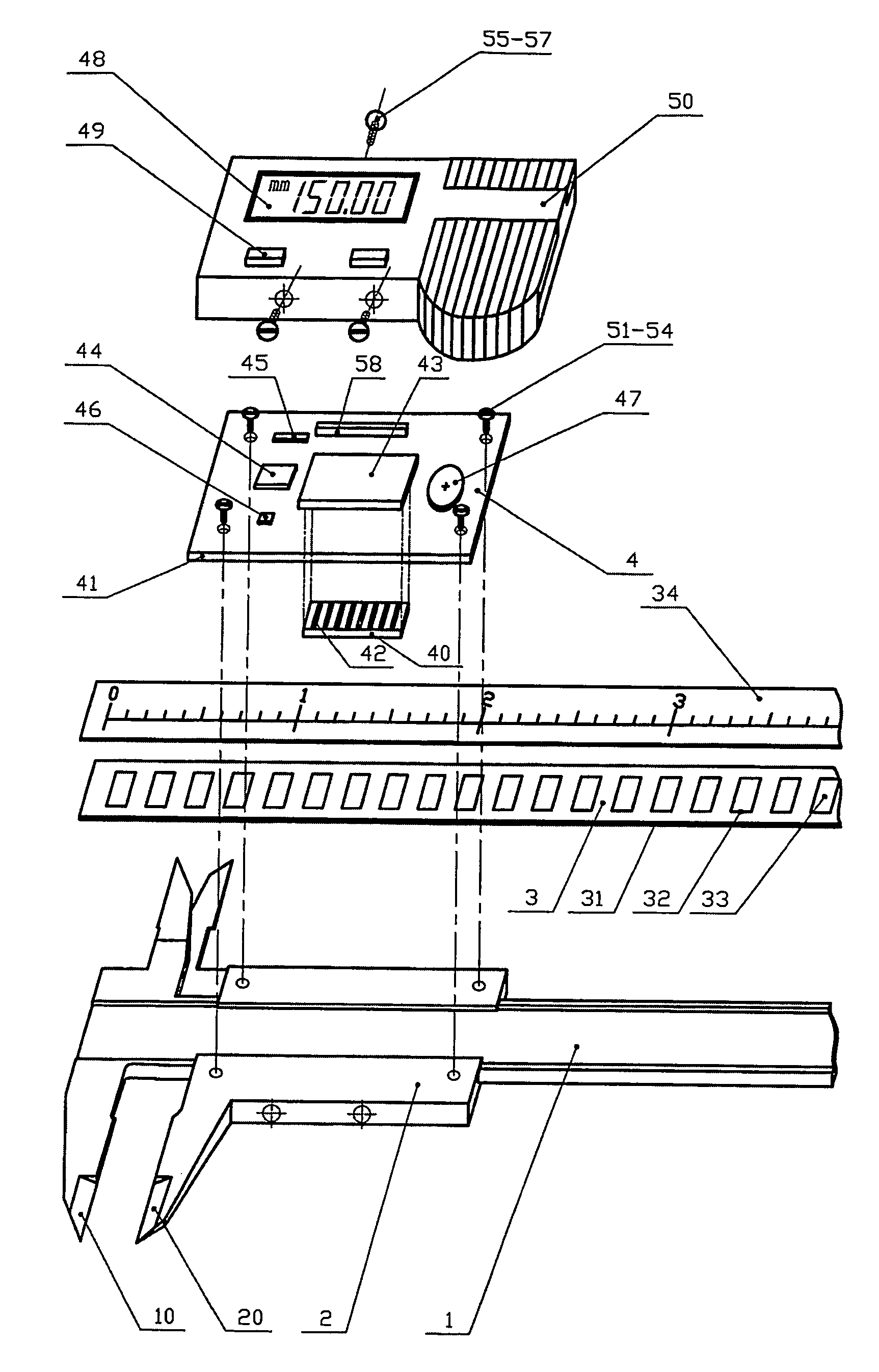
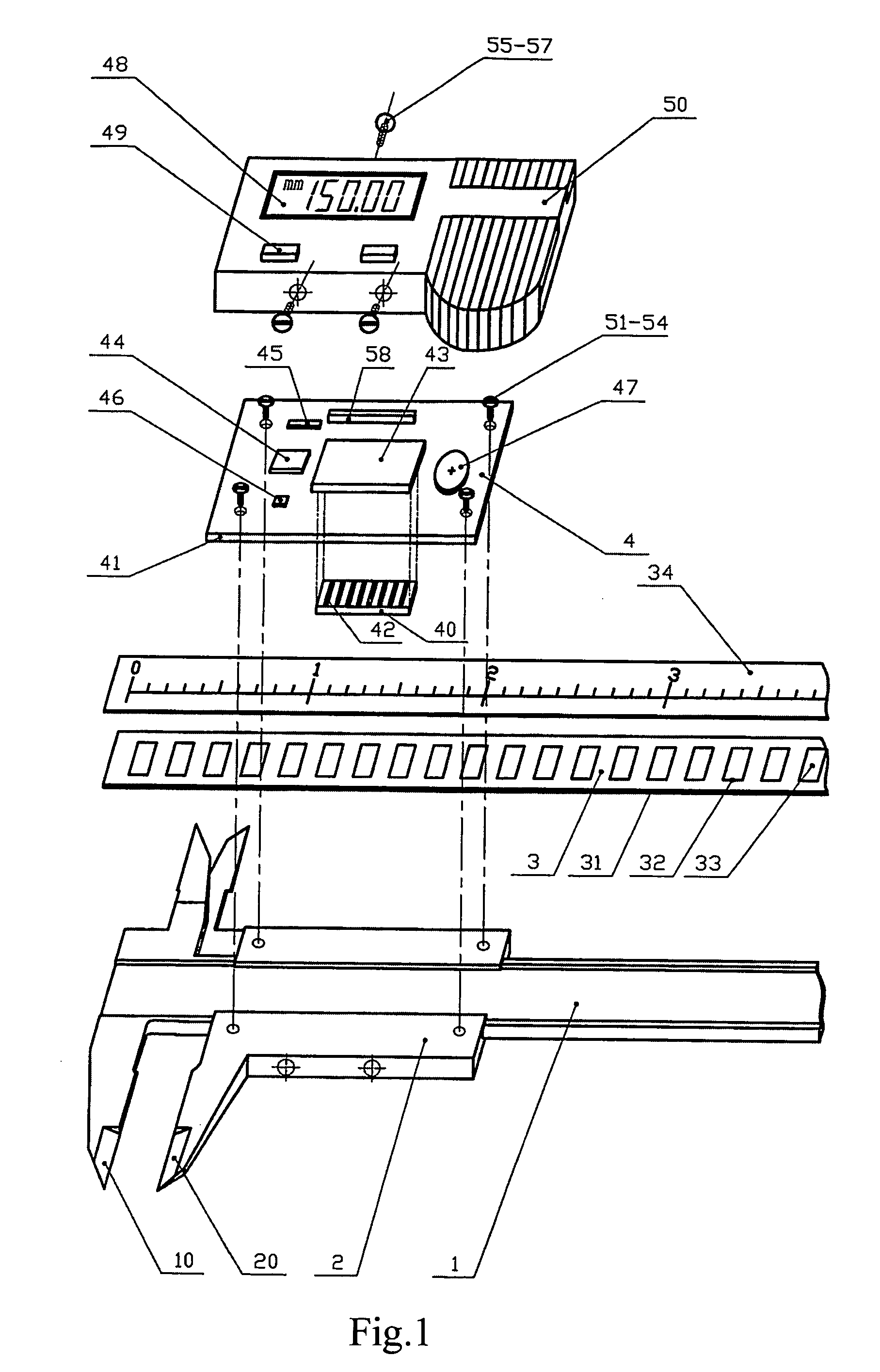
[0043]FIG. 4 shows the main ruler 3. The main ruler 3 are manufactured by the following steps: using non-magnetic printed circuit board (PCB) as a substrate 31; making a mother plate according to the desired grid shape and size; copying the pattern onto a copper foil 32 which has a photosensitive film; then making the copper foil 32 be desired girds with the grid pitch of λ and the width of 0.1-0.5λ by chemical corrosion; finally coating the magnetic material of Nickel onto the surface of the grids by electroplating or chemical plating so as to form the magnetic film 33. the above manufacture method has the advantages of high precision, advanced processing technique, low cost and thin thickness of the main ruler 3, and is well suitable for mass production, especially for producing portable measuring tools. In addition, glass and ceramic may be used as substrate and the magnetic material may be coated onto the substrate according to the pattern of the grids by vacuum plating and etch...
second embodiment
[0044]FIG. 5 shows the main ruler 3. The main ruler 3 is manufactured by the following steps: using non-magnetic material as the substrate 31; making magnetic material be the grids 33 according to the desired grid shape and size by mechanical process, such as punching, milling, linear cutting, etc.; then integrating the grids 33 and the substrate 31 to form the main ruler 3.
third embodiment
[0045]FIG. 6 shows the main ruler 3. The main ruler 3 is manufactured by directly machining the magnetic material into the grids 33. This manufacturing method imposes a higher requirement on the mechanical process.
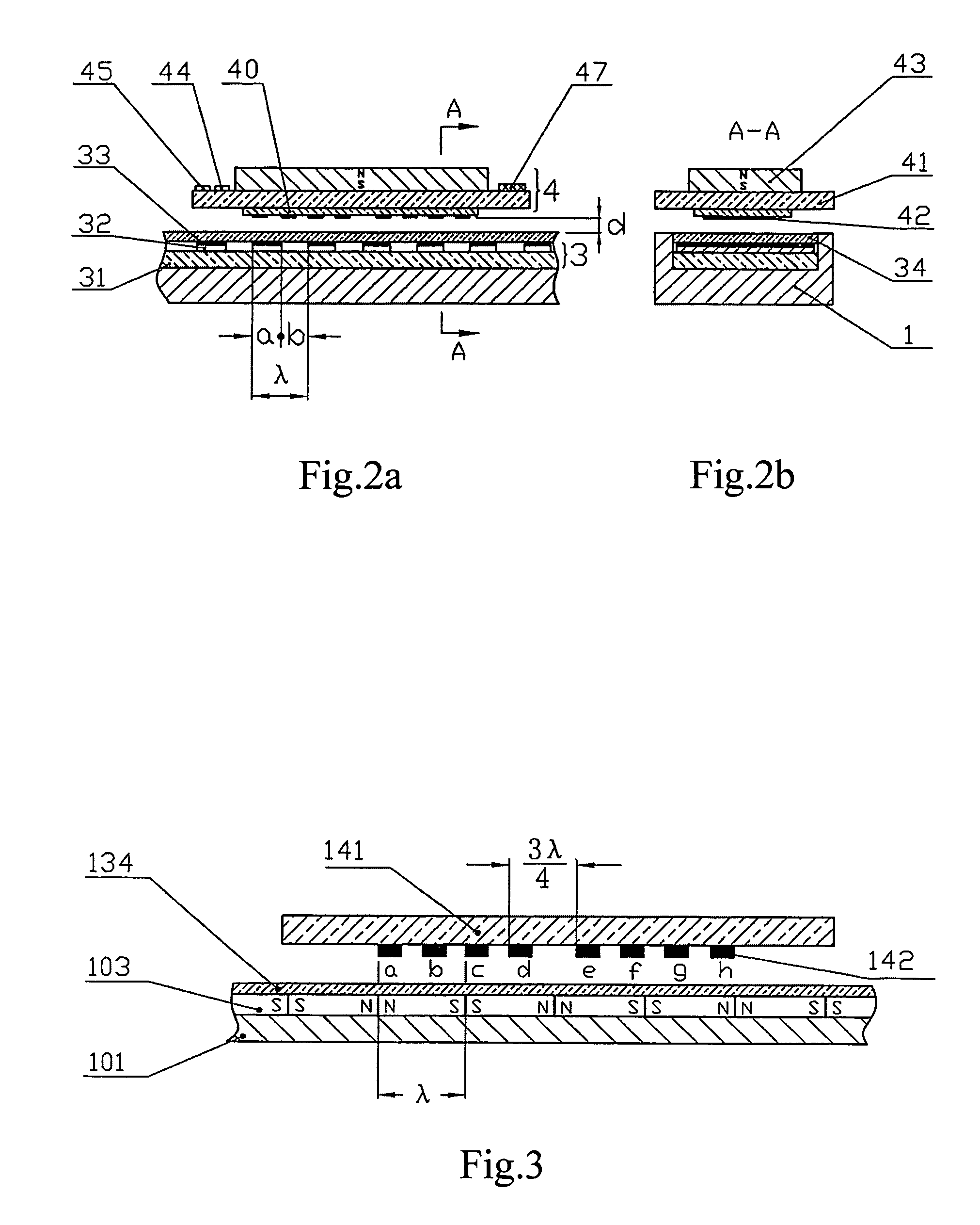
[0046]FIG. 7a shows the first embodiment of the distribution of the magnetoresistances. Two most basic measurement bridges composed of eight magnetoresistances 42a˜42h are shown in the Figure. In practice, in order to reduce the power consumption, these resistors are connected in series, as shown in FIG. 8 and FIG. 9. The magnetoresistances 42a˜42d constitutes the bridge S and the magnetoresistances 42e˜42h constitute the bridge C; and the position difference between the bridge S and the bridge C is nλ / 4, wherein n=1,3,5,7 . . . , so that the measurement circuit may judge the movement direction of the vernier 2. The magnetoresistances in each bridge are arranged at intervals of λ / 2, as shown in FIG. 7, and are connected sequentially to form the bridge as shown in FIG. 11. ...
PUM
 Abstract
Description
Claims
Application Information
 - R&D
- Intellectual Property
- Life Sciences
- Materials
- Tech Scout
- Unparalleled Data Quality
- Higher Quality Content
- 60% Fewer Hallucinations
Browse by: Latest US Patents, China's latest patents, Technical Efficacy Thesaurus, Application Domain, Technology Topic, Popular Technical Reports.
© 2025 PatSnap. All rights reserved.Legal|Privacy policy|Modern Slavery Act Transparency Statement|Sitemap|About US| Contact US: help@patsnap.com


