Magneto-optical resonant waveguide sensors

a technology of magnetic resonance waveguide and magnetic field, applied in the direction of magnetic measurement, instruments, measurement devices, etc., can solve the problems of low sensitivity of most optical materials, lack of proper material form, and signal is thus vulnerable to amplitude variability and interference, and achieve accurate and unambiguous detection, increase measurement sensitivity and resolution, and reduce polarization sensitivity

Inactive Publication Date: 2006-05-18
KYTON
View PDF10 Cites 30 Cited by
  • Summary
  • Abstract
  • Description
  • Claims
  • Application Information

AI Technical Summary

Benefits of technology

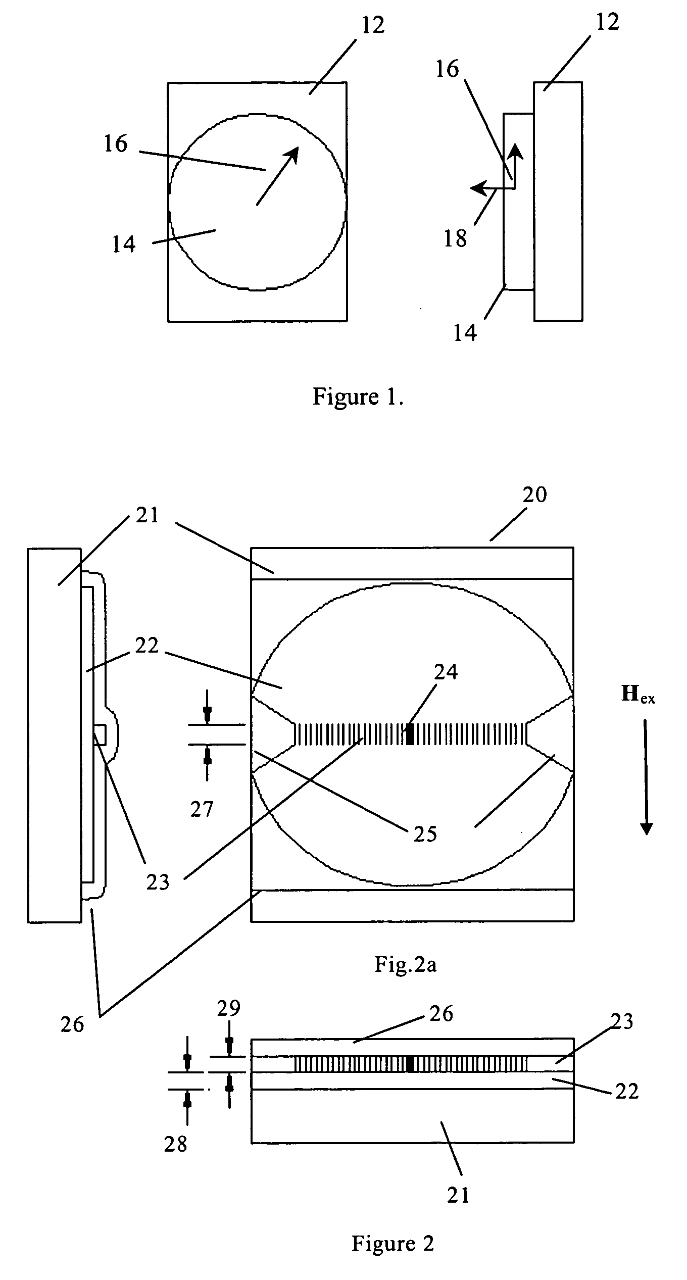
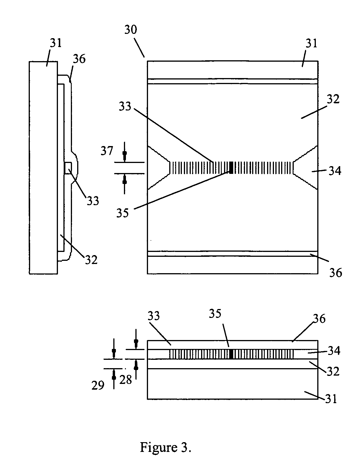
[0010] The illustrative exemplary non-limiting implementations herein provide sensors based on planar optical waveguide resonators with waveguide modes at least partially localized in the one or more layers of materials exhibiting the Faraday Effect (i.e. magneto-optical materials). The magnetization in such magneto-optical materials is preferably the in-plane type of magnetization, i.e., materials in which the magnetization vector lies in, or nearly in, the plane of the wafer from which the sensor is fashioned. Further, the optical waveguide(s) lies in the plane of the wafer as well.
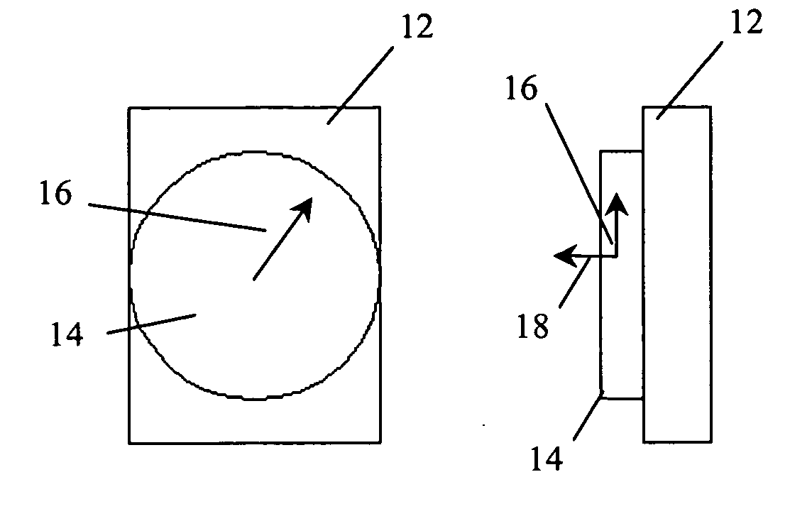
[0011] Exemplary illustrative non-limiting implementations also provide MOFO sensors in which the Faraday Effect material can remain a simple plane-parallel disk shape with no cuts or corners, allowing the magnetization vector to rotate freely in the plane of the sensor disk, greatly increasing the measurement sensitivity and resolution.
[0012] Exemplary illustrative non-limiting implementations can provide MOFO sensors with very few parts (the planar chip, the fiber connections and the package) such that the sensor is robust and stable.
[0013] Exemplary illustrative non-limiting implementations may also provide MOFO sensors that convert the external field magnitude to an optical wavelength shift that is accurately and unambiguously detectable. Further, crossed polarizers are not required, and the polarization sensitivity is reduced to at least the second order, allowing polarization-maintaining fiber connections to eliminate over-all polarization dependence.

Problems solved by technology

This is perhaps partly because of the lack of magnetic sensitivity in most optical materials, lack of the proper form of materials that do have high sensitivity and partly because of the polarization-dependent nature of the sensors that can be made from existing materials.
The signals are thus vulnerable to amplitude variability and interference due to fiber bending losses, dirty connectors and other similar causes, and large inaccuracies can occur.
Polarization-maintaining (PM) fiber can be used to avoid some of the errors due to spurious polarization rotation in the fiber, but cannot solve other amplitude losses.
17), relies on phase measurements but is also vulnerable to amplitude and polarization variability, although not at such a high degree as the Malus scheme.
Another difficulty with prior art Faraday Effect sensors, excluding those of the type based on kilometer-length fiber coils, is that the sensors utilize either relatively large blocks of high Verdet constant glass (several centimeters) or small blocks of a high Faraday Effect material such as perpendicular magnetization Bi:YIG.
In particular with the YIG Faraday Effect sensors, the sensor may be made up of several components (AIRAK, Inc. patent #U.S. Pat. No. 6,534,977) and then glued or otherwise mounted to the fiber, making a fragile and unreliable sensor.
Still further difficulty is found with prior art magnetic field sensors if electrical current is to be measured.
With high voltage power cables, the only way this can be done conveniently is to deliver the sensor with a de-mountable buss bar system—a very costly method.
The same is substantially true of high Verdet constant glass sensors, since the blocks of glass must be fashioned into prisms and placed around the buss bar in a robust holding assembly so the optical path circumvents the buss bar—also a very costly method.
On the other hand, the YIG sensors such as those disclosed in U.S. Pat. No. 6,534,977 are essentially “point” sensors, but suffer from the need to assemble them from many components that must be kept clean and aligned in their package.
This is in addition to the difficulties with amplitude, polarization and sensor robustness discussed above.

Method used


Image

  • Magneto-optical resonant waveguide sensors
  • Magneto-optical resonant waveguide sensors
  • Magneto-optical resonant waveguide sensors

Examples


Embodiment Construction

[0025] An exemplary illustrative non-limiting magneto-optical waveguide sensor is based on MO effects occurring in optical waveguide resonant structures with waveguide modes at least partially localized in the magneto-optical layers, which effects are the so-called nonreciprocal magneto-optic effects of transverse magnetic (TM) waveguide modes [Bahlmann N., Chandrasekhara V., Erdmann A., Gerhardt R., Hertel P., Lehmann R., Salz D., Schroteler F. J., Wallenhorst M., Dotsch H., “Improved design of magnetooptic rib waveguides for optical isolators”, Journal Of Lightwave Technology 16: (5) 818-823 (1998)], [Wallenhorst M., Niemoller M., Dotsch H., Hertel P., Geghardt R., Gather B., “Enhancement of the Nonreciprocal Magnetooptic Effect of TM Modes using Iron-Garnet Double-Layers with Opposite Faraday-Rotation”, JAP, 77: (7) 2902-2905 (1995)]. The physical basis of the sensing mechanism is the dependence of the effective refractive index of the TM mode in the waveguide structure containin...


PUM


Abstract

A waveguide magneto-optic sensor provides a signal indicative of the value and/or direction of a detected magnetic field by a spectral shift of the characteristic resonant spectral feature of the sensor is disclosed. The sensor does not suffer from vibrations, fiber bending or other light intensity noise and provides an absolute self-referencing signal. The sensor elements can easily be coupled to optical fibers and read with scanning spectrometers or scanning lasers calibrated against NIST-traceable gas absorption standards.

Description

CROSS-REFERENCES TO RELATED APPLICATIONS [0001] This application claims the benefit of provisional application 60 / 627,907 filed Nov. 16, 2004, incorporated herein by reference. This application also claims the benefit of commonly assigned copending application Ser. No. 10 / 10 / 316,192 filed Dec. 11, 2002 of Kochergin et al. entitled “MAGNETO-OPTICAL SENSOR EMPLOYING PHASE-SHIFTED TRANSMISSION BRAGG GRATINGS” (attorney docket 340-70) also incorporated herein by reference.STATEMENT REGARDING FEDERALLY SPONSORED RESEARCH OR DEVELOPMENT [0002] Not applicable. FIELD [0003] The technology herein is related to the optical sensing of magnetic fields, including magnetic fields generated by electrical currents. More particularly, the exemplary illustrative non-limiting technology relates to planar waveguide resonator structures, including one or more layers of magneto-optically active material, for the detection of the magnetization changes in magneto-optically active layers by spectral shifts ...

Claims


Application Information

Patent Timeline
Patent Type & Authority Applications(United States)
IPC IPC(8): G01R33/02
CPCG01R33/0322
Inventor KOCHERGIN, VLADIMIRSWINEHART, PHILIPMAKLAD, MOKHTAR
Owner KYTON
Why Eureka
Try Eureka