Bidirectional electro-optical device for coupling light-signals into and out of a waveguide

a waveguide and light-signal technology, applied in the direction of optical waveguide light guides, instruments, optics, etc., can solve the problems of unfavorable interference or scattered signals, very difficult alignment, and very difficult to achieve technicalally, so as to reduce mutual influence or interference

Inactive Publication Date: 2006-05-25
EZCONN
View PDF5 Cites 9 Cited by
  • Summary
  • Abstract
  • Description
  • Claims
  • Application Information

AI Technical Summary

Benefits of technology

[0030] In one embodiment, the carrier has a second side and metallizations for electrical contact-connection of the receiver are formed on the second side of the carrier. T

Problems solved by technology

An essential problem in the provision of bidirectional optoelectronic modules is so-called crosstalk, that is to say undesirable interference or scattered signals that are not intended to be detected by the receiver but are present.
In the case of PLC technology, this can only be

Method used


Image

  • Bidirectional electro-optical device for coupling light-signals into and out of a waveguide
  • Bidirectional electro-optical device for coupling light-signals into and out of a waveguide
  • Bidirectional electro-optical device for coupling light-signals into and out of a waveguide

Examples


Embodiment Construction

[0037] In the figures, mutually corresponding or similar features have the same reference symbols.

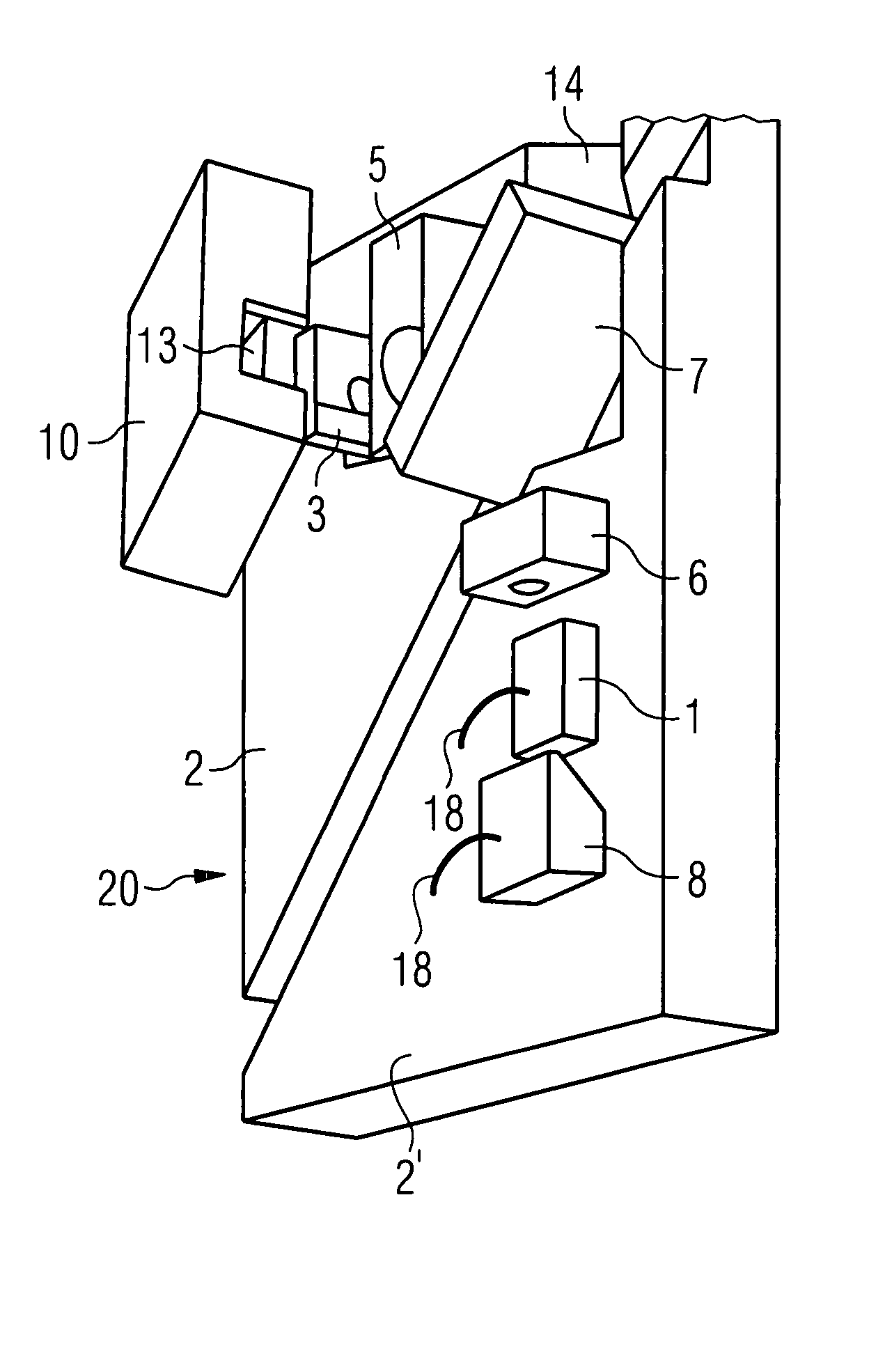
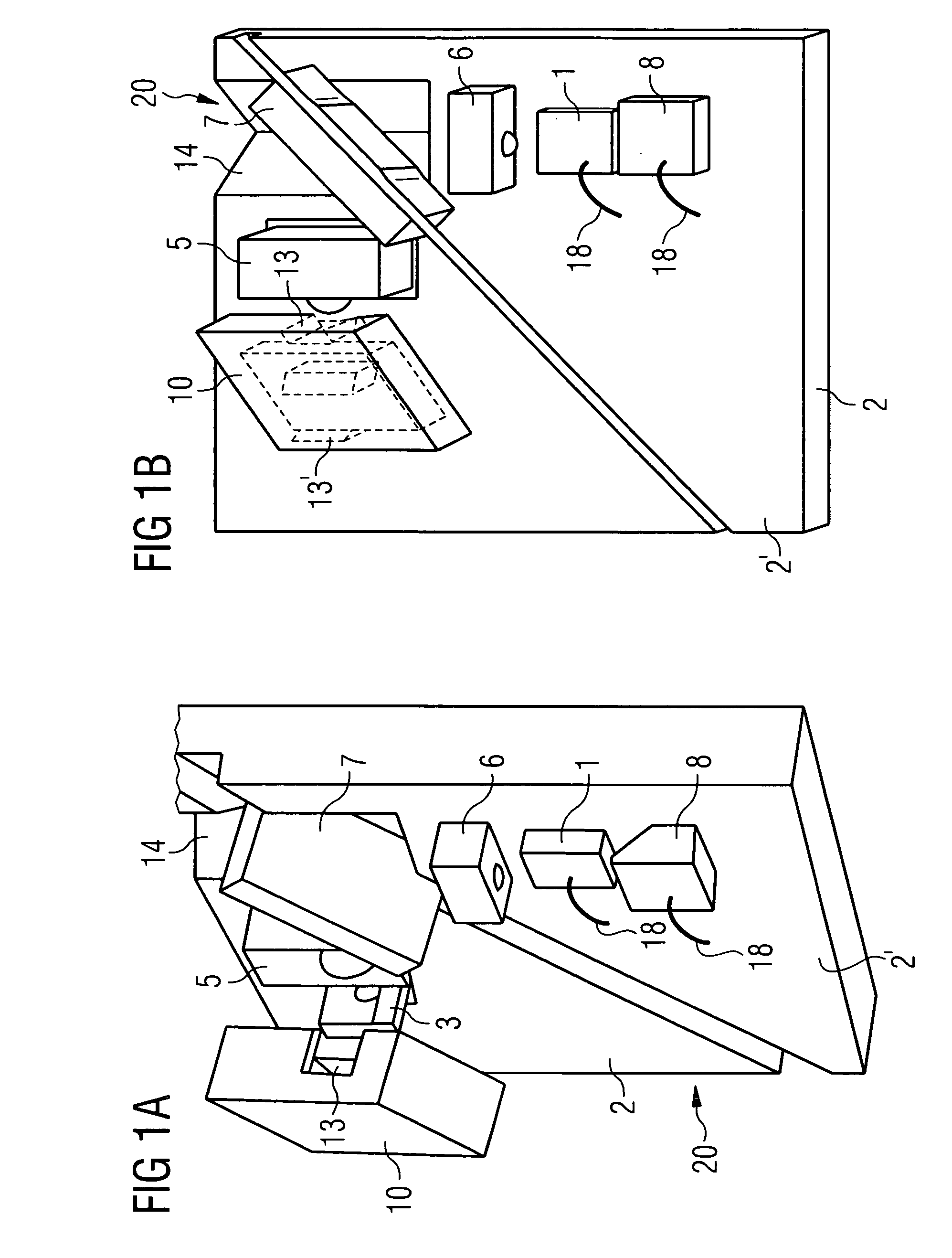
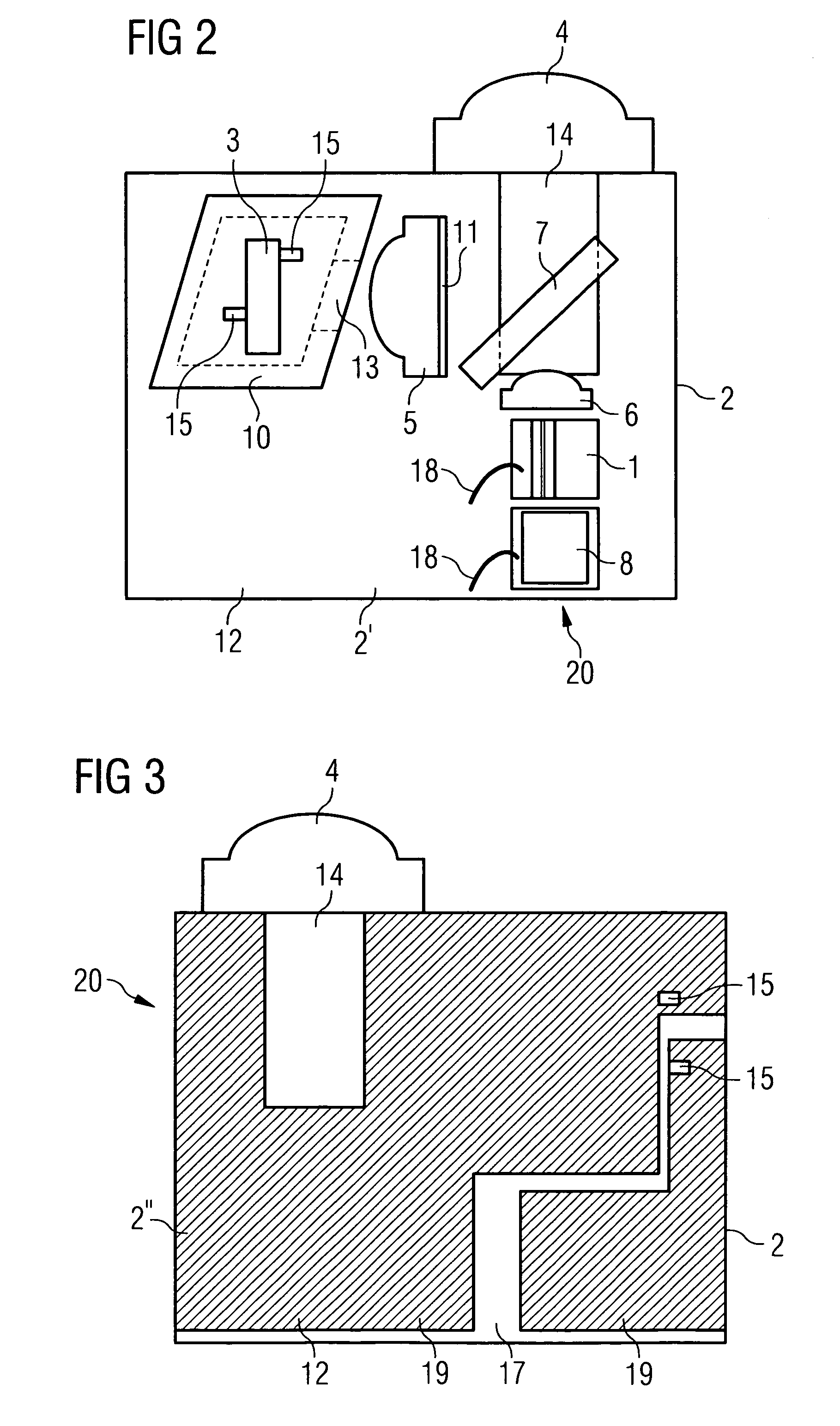
[0038]FIGS. 1a, 1b and 2 show a bidirectional electro-optical transmitting and receiving module 20. The module 20 has a basic carrier plate 2 as carrier, which is formed as a silicon submount, by way of example. All the essential components of the module 20 are arranged on one side, the top side 2′ illustrated in the figures, of the carrier 2.

[0039] A laser diode 1 serves as a light transmitter, whose signal output is recorded by the monitor diode 8. In the further beam course, light signals of the laser diode 1 are detracted by a transmitter microlens 6 and radiate through a wavelength-selective beam splitter 7 before the light signals are coupled out of the module without beam deflection through the microlens 4 (FIG. 2). Light signals that come from the coupling-out direction and are to be detected by the module 20 firstly pass through the microlens 4, are deflected by approximately...


PUM


Abstract

The invention relates to an optoelectronic module for coupling light signals into and out of an optical waveguide. The module has a carrier having at least a first side, a light transmitter for emitting light signals, which is arranged on the carrier, a receiver for detecting light signals, which is arranged on the carrier, and a beam-shaping element for coupling light signals of the laser diode out of the module and for coupling light signals into the receiver. The light transmitter and the receiver are both arranged on the first side of the carrier, a shielding means serving to shield the receiver from optical and/or electrical interference signals. As a result, a bidirectional optoelectronic module is provided which is distinguished by signal conversion that is as precise as possible and, at the same time, is comparatively cost-effective in terms of production.

Description

[0001] The invention relates to an optoelectronic module for coupling light signals into and out of an optical waveguide. In particular, the invention relates to an optoelectronic micromodule arrangement that is employed in the field of micromodule technology. BACKGROUND OF THE INVENTION [0002] Bidirectional optoelectronic transmitting and receiving modules (transceivers) which can both transmit and receive optical signals are known. Bidirectional modules based on micromodule technology are used in particular as TO components (TO=transistor outline). A bidirectional transmitting and receiving module transmits light having a first wavelength and detects light having a second wavelength. A preferred, but not exclusive, area of use is WDM (wavelength division multiplex / demultiplex) communications. [0003] It is furthermore known to use, for a compact construction, bidirectional transmitting and receiving modules that use a common carrier for the light transmitter and the receiver. In or...

Claims


Application Information

Patent Timeline
IPC IPC(8): G02B6/12
CPCG02B6/29361G02B6/4206G02B6/4246
Inventor BACHL, BERNHARDBROCKHAUS, PETER
Owner EZCONN
Why Eureka
Try Eureka