
Systems and methods for laser material manipulation

a laser and material technology, applied in the field of systems and methods for laser material manipulation, can solve the problems of insufficient microstructures of current and near-future silicon-based integrated circuit technologies and other types of microstructures, thermal damage on the micrometer scale of typical laser machining using relatively longer pulses,

Inactive Publication Date: 2006-06-08
CHOSEN TECH
View PDF12 Cites 46 Cited by
  • Summary
  • Abstract
  • Description
  • Claims
  • Application Information

AI Technical Summary

Benefits of technology

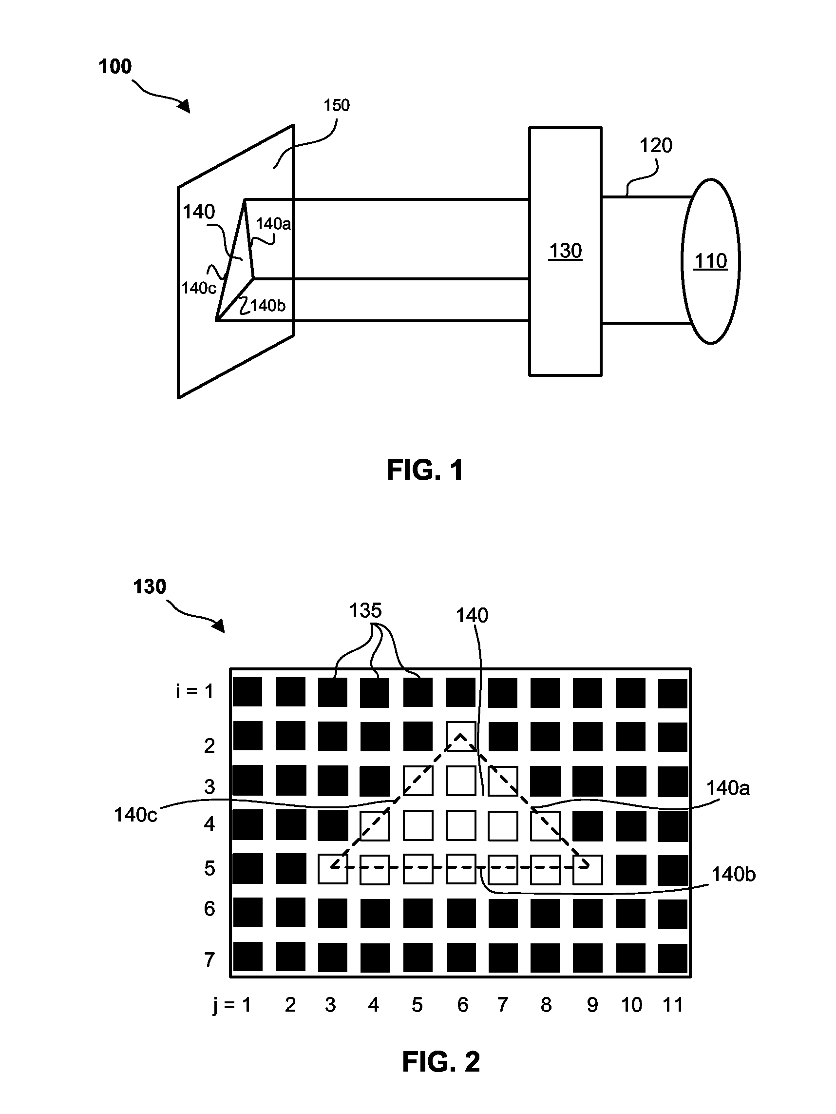
[0010] In one embodiment, the array of controllable imaging elements are individually controllable, and each controllable imaging element has at least two different statuses, each status effectuating a distinctive optical effect on a laser pulse that interacts with the controllable imaging element. The array of controllable imaging elements may further be addressable by an addressing controller, as that in a video display such as LCD and DLP.

Problems solved by technology

The phenomenon of laser ablation of a material has been known and studied for years, but the results with older nanosecond-regime laser technologies operating at one billionth of a second (10−9 sec) would not have sufficed for the small structures of current and near-future silicon-based integrated-circuit technologies and other types of microstructures such as nanotechnology.
Typical laser machining using relatively longer pulses tends to leave thermal damage on the micrometer scale.
For devices having a size scale near or under micrometers, thermal damage is generally unacceptable.

Method used


Image

  • Systems and methods for laser material manipulation
  • Systems and methods for laser material manipulation
  • Systems and methods for laser material manipulation

Examples


Embodiment Construction

[0023] To better understand the present invention, it is helpful to discuss an inherent shortcoming of the conventional laser cutting / ablation processes using a focused laser beam to remove a surface material on a small spot where the laser beam is focused on. In the conventional method, the ablation point and depth are controlled via changing the focus and moving a galvanizing mirror. The cutting or ablation progresses in a point-by-point manner, resulting in a slow and inefficient process. In some alternative applications, a simple mechanical mask has been used to project the laser on to the target. This however still result in an inefficient and highly inflexible system and process.

[0024] As will be demonstrated in the following representative embodiments, the present invention improves the existing laser ablation systems and methods by providing a laser material manipulation system that uses a laser imaging device having an array of controllable imaging elements. The laser imag...


PUM

PropertyMeasurementUnit
sizeaaaaaaaaaa
sizeaaaaaaaaaa
transparencyaaaaaaaaaa

Abstract

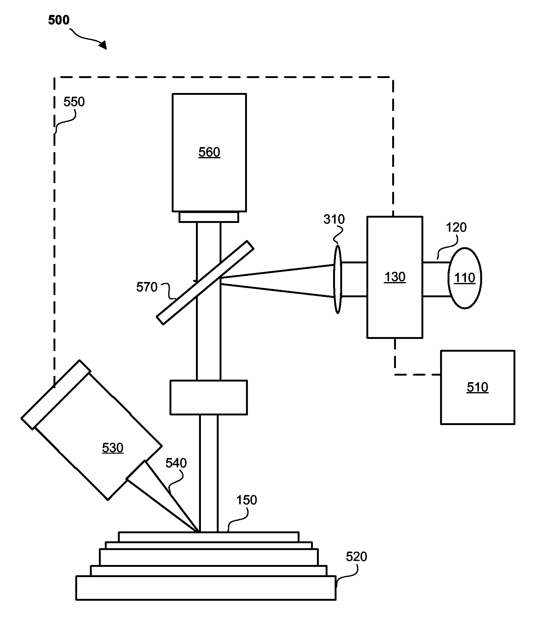
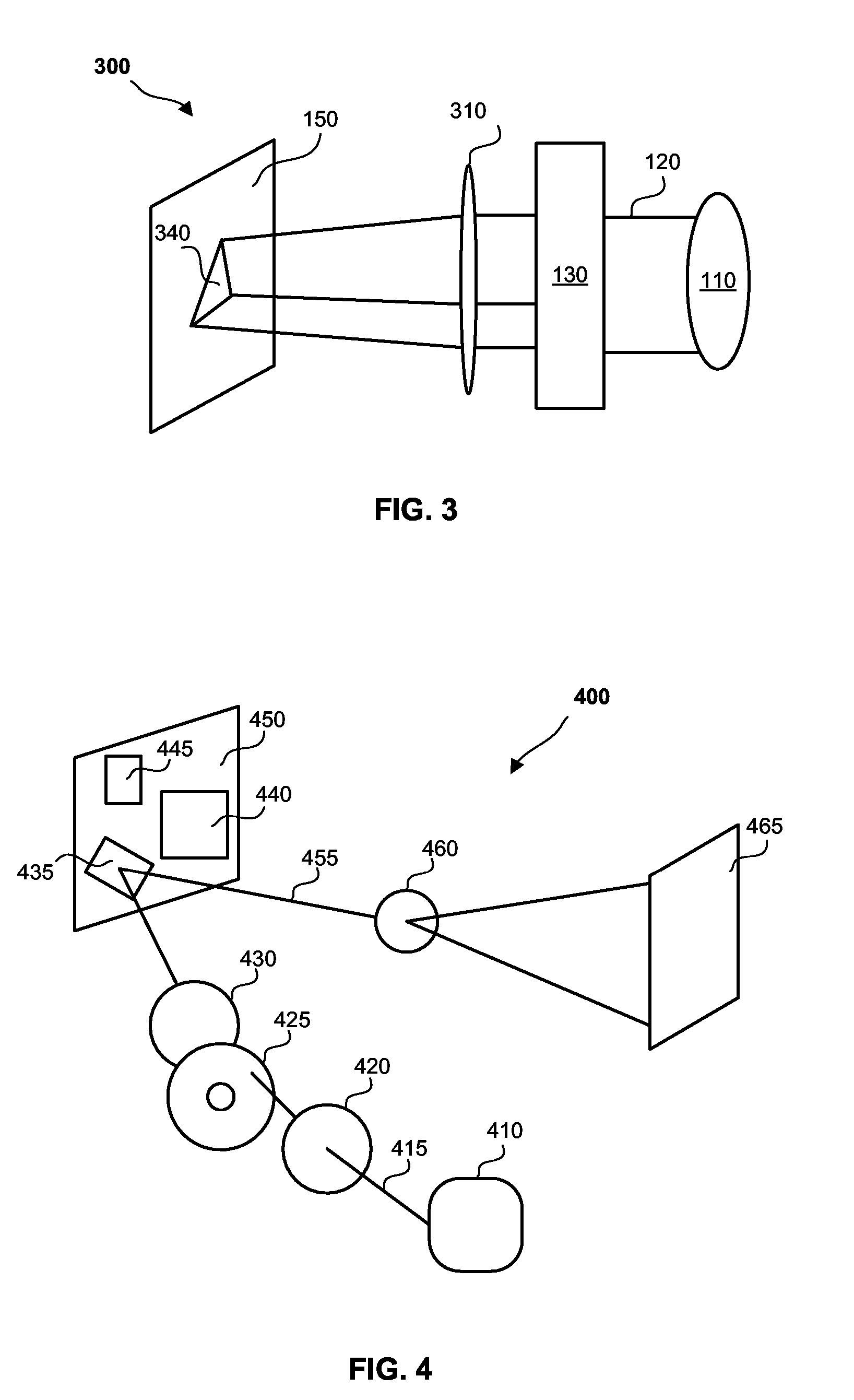
A laser material manipulation system is provided for material manipulations such as laser ablation, laser deposition and laser machining. The system includes a laser for emitting laser pulses and a laser imaging device having an array of controllable imaging elements. The laser imaging device receives the laser pulses emitted from the laser, forms a laser image through the controllable imaging elements, and projects the laser image onto a target material which needs to be manipulated. The projected laser image manipulates the material according to a desired manipulation pattern. The laser can be a femtosecond laser. The laser imaging device can be a liquid crystal display (LCD) or a digital micromirror device (DMD). An SEM can be used for monitoring the material distribution and dynamically adjust the laser image according to the monitor result.

Description

CROSS-REFERENCE TO RELATED APPLICATIONS [0001] This application claims benefit of an earlier filing date of U.S. provisional patent application, Ser. No. 60 / 633,814, filed Dec. 7, 2004, entitled “Systems and Methods for Laser Ablation”.BACKGROUND [0002] 1. Field of the Invention [0003] The present invention relates generally to systems and methods for laser manipulation such as laser ablation, and particularly to systems and methods for small scale processes, such as semiconductor inspection, device editing, microsystem modification, sample preparation and MEMS manufacturing using laser. [0004] 2. Description of the Prior Art [0005] Laser has been used to manipulate materials in a variety of ways. This includes laser ablation (material removal or a subtraction process), laser deposition (an additive process), laser machining, laser milling, and laser inspection (often combined with laser cutting). Laser is increasingly substituting or supplementing focused ion beam (FIB) milling, an...

Claims


Application Information

Patent Timeline
Patent Type & Authority Applications(United States)
IPC IPC(8): H04N5/74
CPCB23K26/03B23K26/032B23K26/0635B23K26/0656B23K26/0624B23K26/066
Inventor LIN, SHIH-CHAO
Owner CHOSEN TECH
Learn More