
Modular drug delivery system

a drug delivery system and module technology, applied in the direction of infusion needles, process and machine control, instruments, etc., can solve the problems of complex user experience, cumbersome loading of the cartridge into the pump mechanism, and limited use of insulin pumps, so as to achieve high degree of flexibility, cost-effective and efficient

Inactive Publication Date: 2006-06-08
POULSEN JENS ULRIK +1
View PDF17 Cites 224 Cited by
  • Summary
  • Abstract
  • Description
  • Claims
  • Application Information

AI Technical Summary

Benefits of technology

[0027] Having regard to the above discussion of known infusion devices, the object of the present invention is to provide a concept for a drug delivery device and system providing a high degree of flexibility for both the user and manufacturer, allowing the user to modify the infusion device or system to better suit the given and changing circumstances, and allowing the manufacturer to provide this flexibility in a cost effective and efficient manner.
[0033] The set of commands provided by the control means or the local processor means may comprise one or more commands controlling the expelling means. In a simple configuration the “set” of commands comprises a single command which would control the expelling means to expel drug contained in the reservoir corresponding to a pre-determined constant delivery rate, e.g. a basal rate, however, several such commands providing different delivery rates or profiles may be provided in combination with other commands. The expelling commands may also comprise one or more bolus commands by which a given volume of drug is infused over a shorter period of time. In addition to commands controlling the expelling means numerous other commands may be provided, e.g. display commands may control display means, memory commands may control in- and output from memory means, sensor commands may control sensor means, alarm commands may control alarm means, and transmission commands may control the transmission of data information.
[0036] By providing a control processor the flexibility of the system is enhanced, e.g. by means of the control processor an advanced interface between the user and the available control commands can be established just as received data information can be stored, processed and used to generate new control commands.
[0067] As discussed above, the actual mechanical, electrical and electronic interface between the two units is decided during a normal design procedure, however, the interface should designed in such a way, that the highest degree of constructional freedom is provided for both of the units, allowing the “controlling capabilities” of the control unit to be varied from very complex versions to very simple versions.
[0074] By (also) providing a disposable control unit a number of advantages is achieved from the sight of the manufacturer as well by allowing a large number of variants to be produced and distributed in an effective manner. For example, different versions of the reservoir unit as well as different versions of the control unit may be produced at different locations and shipped independently of each other to a given location, where the units may be assembled, for example at the point of sale. In this way cheap or expensive versions of the two units may be combined as desired. When the control unit is sold as a disposable component, the mating coupling means may be adapted to permanently secure the control unit to the housing preventing the reuse of the control unit. Actuating the system to start drug delivery may be by further manipulation of the control unit (e.g. pressing or turning) or by additional means provided on the reservoir unit. In this way it would be possible to produce one or more control units which just prior to installation are given a functionality corresponding to either a cheap or a more expensive version.

Problems solved by technology

However, the use of insulin pumps has been rather limited as the pumps have been expensive to manufacture as well as complex to operate.
In an attempt to provide improved user friendliness, an early infuser used a cartridge similar to the ones used in the pen devices which meant that loading of the cartridge into the pump mechanism was rather cumbersome just as the need to keep track of the batteries not running flat added to the complexity experienced by the user.
Further, as more and more programming features were added, this complexity alone made the infusers unsuitable for certain group of users.
An early example can be found in WO 85 / 00523 teaching to integrate the power source for the pump into a disposable unit, however, the disposable unit further comprises an infusion line for insertion into a pump head to provide a peristaltic pump, this complicating the mounting of the disposable unit.
Although this type of device provides for improved convenience and safety of use, it would normally be considered too costly to incorporate advanced functions such as flow measurement, display means or the ability to cooperate with a remote control unit.
The user may also choose a smaller device which typically can be attached to the skin of the user by an adhesive, however, such infusion devices are normally rather small, with restricted capabilities in programmability.
Indeed, it may be argued that it would be possible to attach a smaller reservoir unit to the larger type of infusion device, or to attach a larger reservoir unit to the smaller type of infusion device, however, this would hardly solve the problem as such infusion devices merely would be “a large infusion device with a small reservoir attached” or “a small infusion device with a large reservoir attached”; correspondingly, such infusion devices are not known in to the present inventors.
However, in practise this approach is not considered attractive by most users for a number of reasons, for example, most users prefer to get accustomed with only one type of infusion device, just as swapping between a number of different devices would make it difficult to keep track of the amount of drug infused.
From the point of the manufacturer, the practise hitherto pursued means that once it is decided to which “class” a given infusion device belongs, i.e. small or large, expensive or cheap, advanced or simple, it will be difficult and / or expensive to adopt a given device to suit other purposes.
Indeed, a given manufacturer may choose to develop two or more different infusion devices each belonging to a given class of devices as discussed above, however, this approach has at least two drawbacks.
Firstly, it will be expensive to both develop and keep a number of systems technologically updated, and secondly, the user may choose different devices from different suppliers, this meaning loss of business as well as loss of brand loyalty.

Method used


Image

  • Modular drug delivery system
  • Modular drug delivery system
  • Modular drug delivery system

Examples


first embodiment

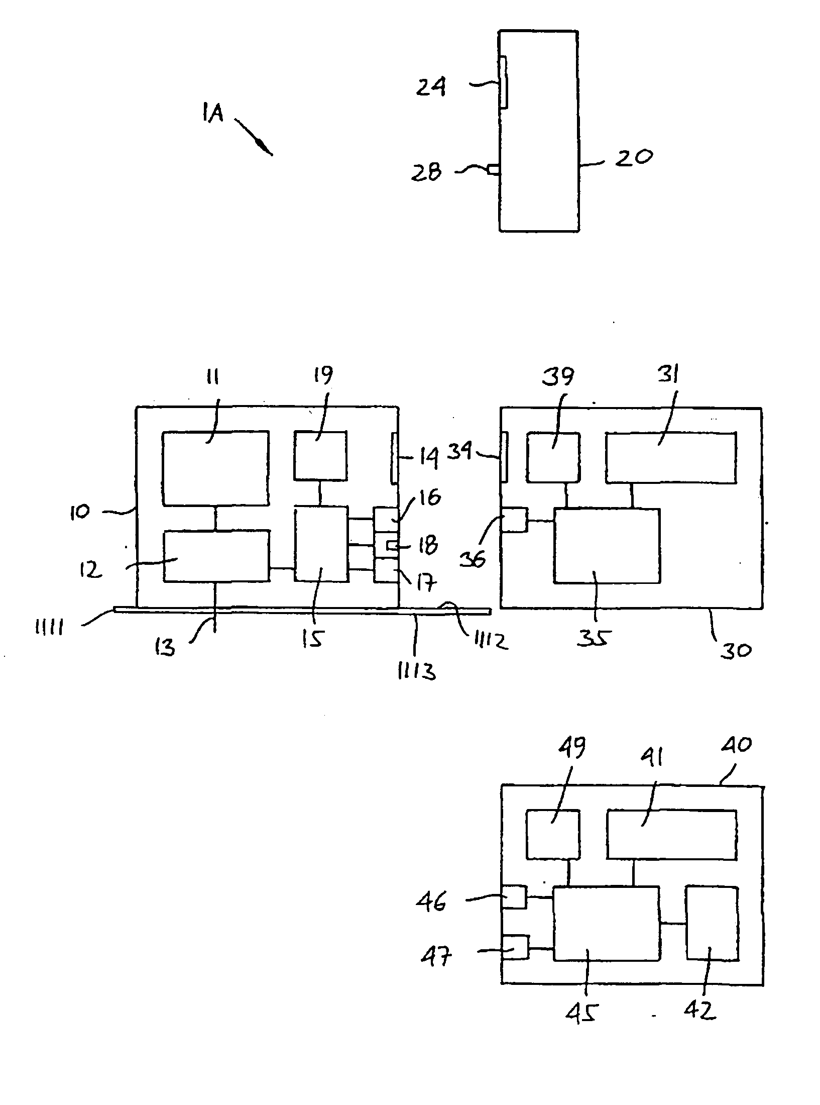
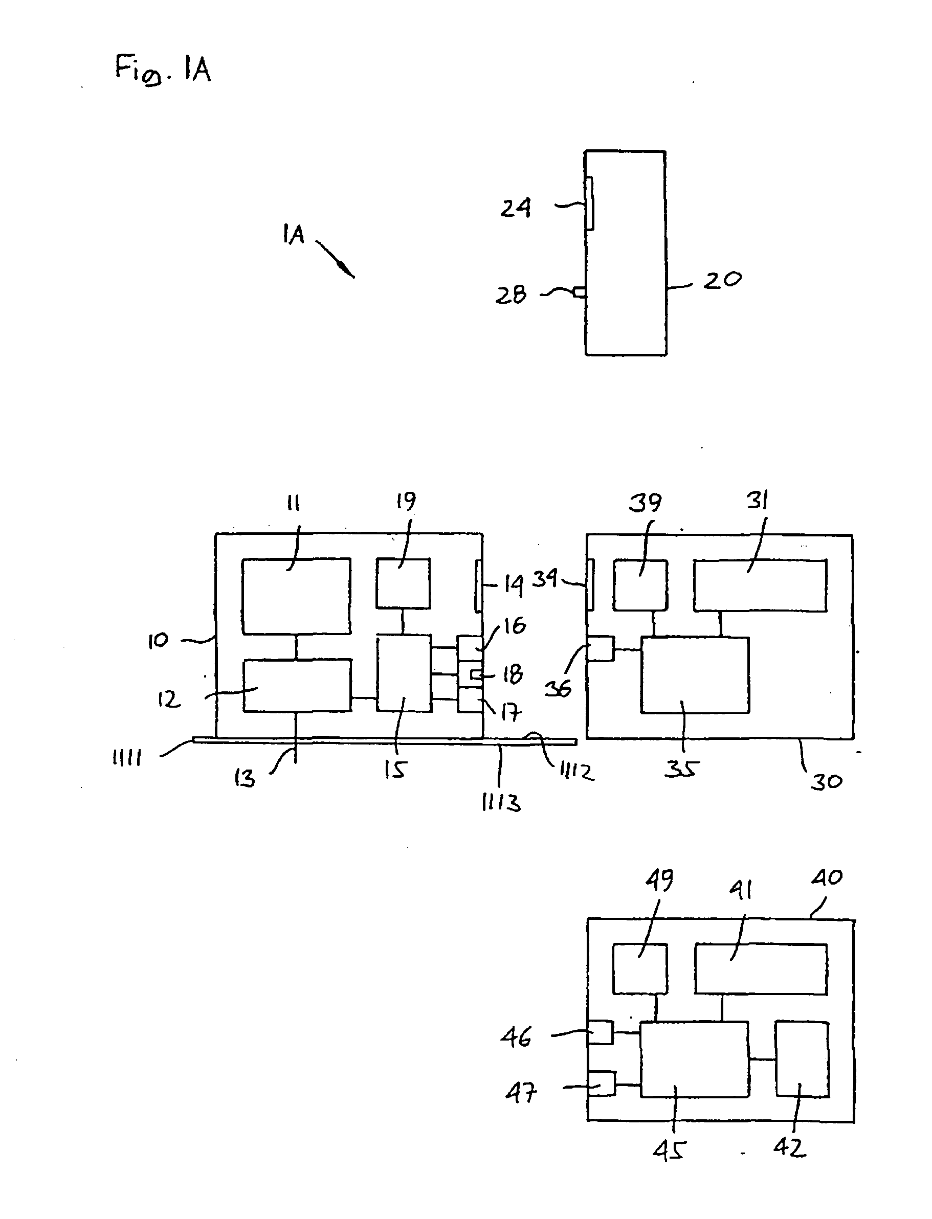
[0091]FIG. 1A shows a schematic representation of the invention. Correspondingly, the configuration of the different structures as well as there relative dimensions and locations are intended to serve illustrative purposes only.

[0092] More specifically, a drug delivery system (here: infusion system) 1B comprises a reservoir unit 10 in combination with three different control units 20, 30, 40, in which a combination of the reservoir unit and one of the control units provides an operative drug delivery device.

[0093] The reservoir unit comprises a drug reservoir 11 and a pump 12 comprising an outlet means 13 and adapted for infusing a drug into a body of a user in accordance with instructions (i.e. a local command) received from a local processor 15. The pump may be of the metering type, i.e. the amount of drug infused corresponds to the controlling signals received from the local processor or the infusion unit may be provided with detecting means for determining the amount of drug ac...

second embodiment

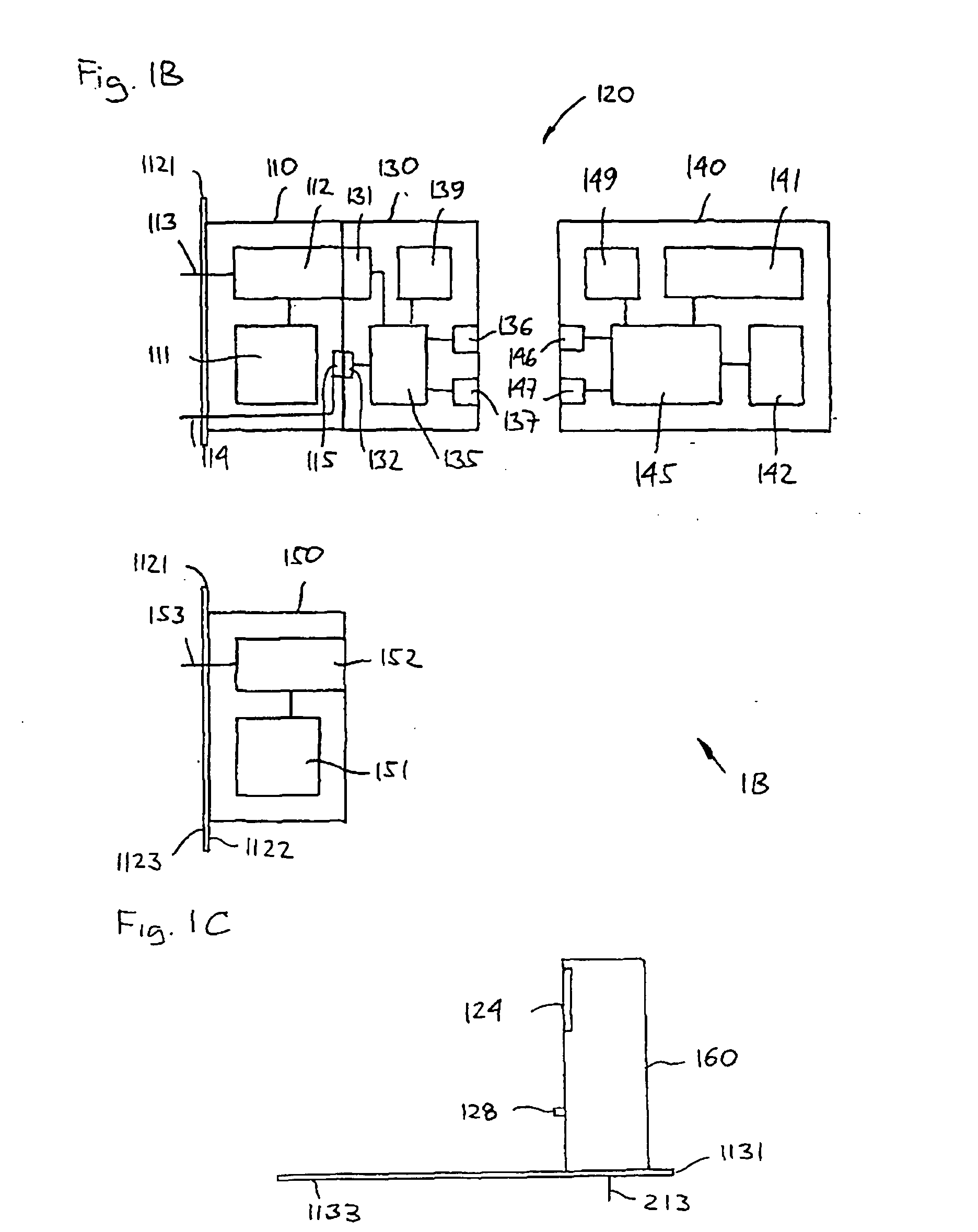
[0108]FIGS. 2A and 2B show the invention. More specifically, a drug delivery (here: infusion) system 2 comprises a reservoir unit 200 in combination with two different control units 250, 260, in which a combination of the reservoir unit and one of the control units provides an operative drug delivery device.

[0109] The reservoir unit comprises an outer housing defining the outer boundaries for the combined infusion device, the housing having an upper surface 201, a rim portion 202 and a lower surface 203 adapted to be arranged towards a skin surface of a user. Preferably the lower surface is provided with an adhesive (not shown) allowing the device to be attached directly to the skin surface. In the upper surface an opening 204 is provided adapted to receive a control unit, the reservoir unit and the control units including mating coupling means 205, 255, 265 so as to allow a control unit to be secured to the reservoir unit, the mating coupling means including electrical contacts 206...

third embodiment

[0117]FIGS. 3A and 3B show the invention. More specifically, a drug delivery (here: infusion) system 3 comprises a reservoir unit 300 in combination with three different control units 350, 360, 370 in which a combination of the reservoir unit and one of the control units provides an operative drug delivery device.

[0118] The reservoir unit comprises an outer housing defining the outer boundaries for the combined infusion device, the housing having an upper surface 301, a rim portion 302 and a lower surface 303 adapted to be arranged towards a skin surface of a user and preferably being provided with an adhesive. The reservoir unit is provided with a “cut-out” portion 304 adapted to receive a control unit, the reservoir unit and the control units including mating coupling means 305, 355, 365, 375 so as to allow the control unit to be secured to the reservoir unit, the mating coupling means including electrical contacts. As can be seen, the lower portion comprises an extension in the f...


PUM


Abstract

The invention relates to a modular drug delivery system, comprising a reservoir unit and a control unit in combination with at least one further reservoir or control unit, whereby each combination of a reservoir unit and a control provides different capabilities. More specifically, the present invention provides a system for delivering a drug to a user, comprising a reservoir unit, a control unit, and at least one further reservoir unit or control unit, wherein each reservoir unit is adapted to receive at least one command from a control unit and perform an action in response thereto, and comprises a reservoir adapted to contain a liquid drug and includes, in a situation of use, associated outlet means. The system further comprises expelling means for expelling a drug out of the reservoir through the outlet means. Each control unit comprises control means providing one or more commands for controlling the operation of a reservoir unit, wherein each combination of a reservoir unit and a control unit is adapted to provide a system with different capabilities.

Description

CROSS REFERENCE TO RELATED APPLICATIONS [0001] This application claims priority under 35 USC §119 of Danish Application No. PA 200101403, filed Sep. 26, 2001 and of U.S. Provisional Application No. 60 / 327,117, filed Oct. 4, 2001, and is a Continuation in Part of U.S. Ser. No. 10 / 256,564, the contents of all three applications are hereby incorporated by reference in their entirety. [0002] The contents of co-owned U.S. application Ser. No. 60 / 518,836 and PCT WO 2005 / 039673, which contain related subject matter, are hereby also incorporated by reference in their entireties.BACKGROUND OF THE INVENTION [0003] The invention relates to a modular drug delivery system, comprising a reservoir unit and a control unit in combination with at least one further reservoir or control unit, whereby each combination of a reservoir unit and a control unit provides different capabilities. The system may be adapted for subcutaneous or intra-dermal infusion of a liquid formulation of an active ingredient ...

Claims


Application Information

Patent Timeline
IPC IPC(8): A61K9/22A61M5/14A61M5/142A61M5/158A61M5/168G16H20/17
CPCA61M5/1413A61M5/14244A61M5/14248A61M5/16827A61M2005/14208A61M2005/14268A61M2005/1581G06F19/3468A61M5/142A61M5/158A61M5/168A61M5/172A61M2205/33A61M2205/502G16H20/17
Inventor POULSEN, JENS ULRIKKRAG-JENSEN, CHRISTIAN
Owner POULSEN JENS ULRIK
Learn More