Screen printing machine and printing method thereof

a screen printing machine and printing method technology, applied in printing, coatings, inking apparatus, etc., can solve the problems of rubbing and printing defects, difficult printing of solder bumps to high density multi-layered substrates, positioning errors of screen s with regard, etc., and achieve high rigidity and high density

Inactive Publication Date: 2006-06-15
DENSO CORP
View PDF6 Cites 18 Cited by
  • Summary
  • Abstract
  • Description
  • Claims
  • Application Information

AI Technical Summary

Benefits of technology

[0013] According to one aspect of the invention, there is provided a screen printing machine, wherein a printing mechanism for printing paste to a work through a screen mask includes a mechanism having a packing head equipped at its distal end with a packing nozzle coming into contact with the screen mask and moving on the screen mask to thereby conduct printing; and a feed tank for supplying the paste into said packing head; each of the packing head and the feed tank having therein an extrusion mechanism capable of controlling an extrusion pressure of the paste to the screen mask. Accordingly, the paste can be pressurized and discharged very precisely from the packing nozzle and printing of high density minute bumps becomes possible.
[0014] In the printing machine according to the invention, the packing nozzle is formed of a material having high rigidity, the packing head is supported by a packing head supporting mechanism capable of moving up and down the packing head and a pushing forc

Problems solved by technology

When the solder bump printing technology according to the prior art is employed to satisfy such a requirement, a suitable packing operation angle θ cannot be kept at a minute bump diameter φ (φ=0.1 mm) corresponding to the lip radius R (R=0.1 mm, for example) in minute bump printing shown in FIG. 7B, and rubbing and printing defects occur.
The thickness t of the screen S has changed from 200 μm of the pri

Method used


Image

  • Screen printing machine and printing method thereof
  • Screen printing machine and printing method thereof
  • Screen printing machine and printing method thereof

Examples


Embodiment Construction

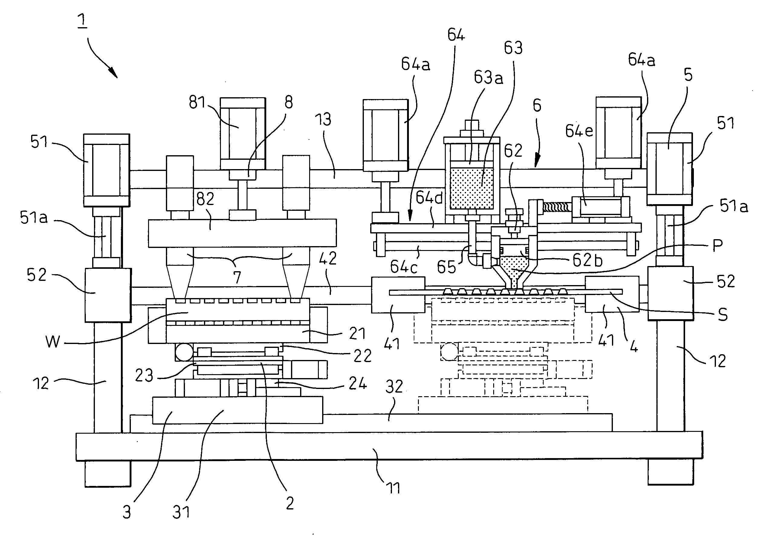
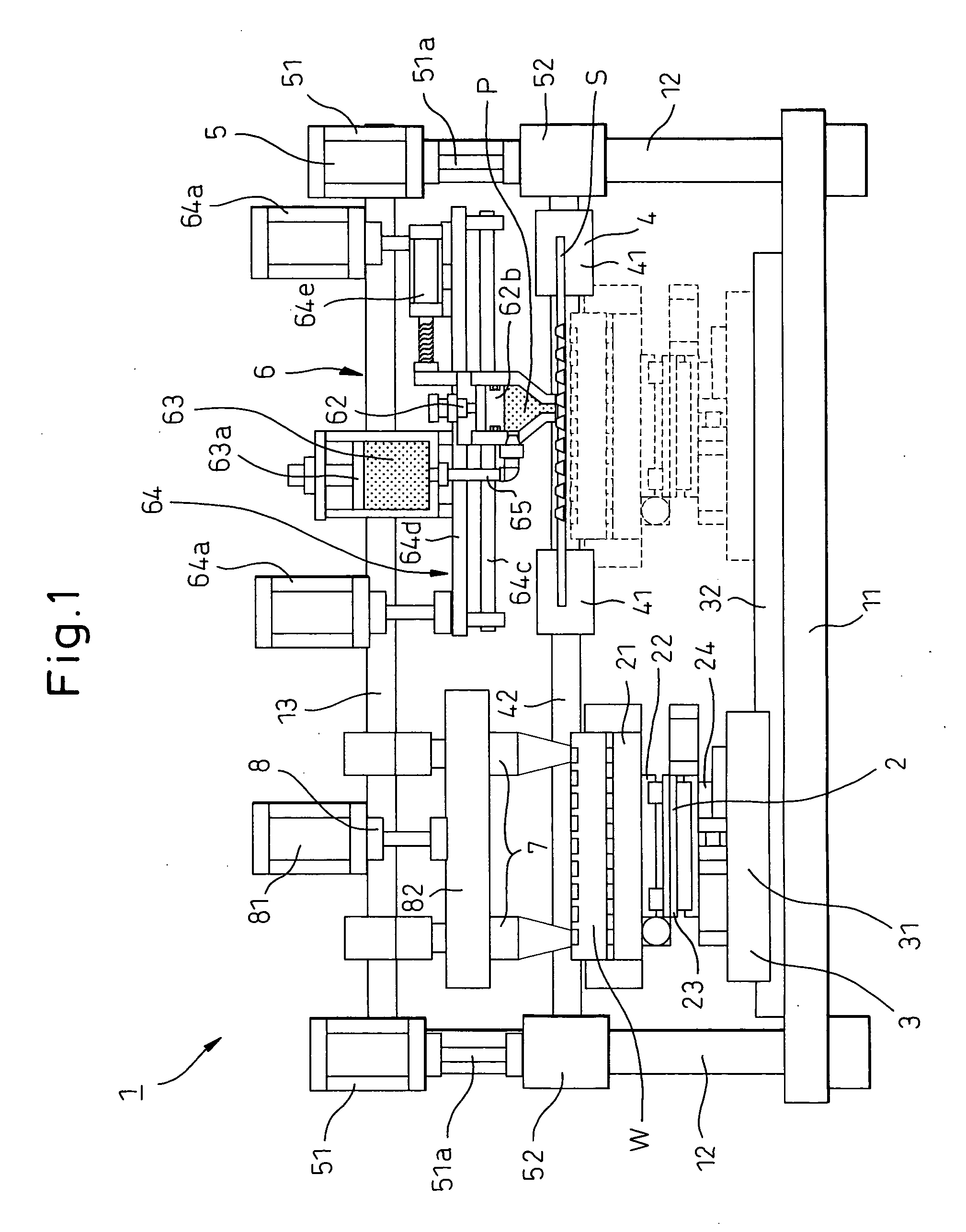
[0027] A screen printing machine and its printing method according to embodiments of the invention will be hereinafter explained with reference to the accompanying drawings. FIG. 1 is a view showing an overall construction of a screen printing machine according to the embodiment of the invention and FIG. 2 is an enlarged view of a printing mechanism as a main portion of FIG. 1. The screen printing machine 1 basically includes a work alignment mechanism 2 for positioning a work W as a substrate in X, Y, θ directions, a work moving mechanism 3 for linearly moving the work W between a work alignment position and a printing position, a screen moving mechanism 4 for linearly moving a screen S (screen mask) between the work alignment position and the printing position, a screen elevation mechanism 5 for moving up and down the screen S, a printing mechanism 6 for printing a solder paste P on the work W at the printing position through the screen S, an image processing camera 7 for imaging ...


PUM


Abstract

A printing mechanism 6 of a screen printing machine 1 for printing paste P at a printing position to a work W through a screen S includes a packing nozzle 62 coming into contact, at the distal end thereof, with the screen, a packing head 62 to which the paste consumed during printing is packed and a feed tank 63 for supplying the paste to the filling head. Each of the packing head and the feed tank has therein an extrusion mechanism 62b, 63a and can control an extrusion pressure of the paste to the screen. The printing mechanism further includes a packing head supporting mechanism 64 capable of supporting the packing head in such a manner as to be capable of moving up and down and also capable of regulating the pushing force of the packing head onto the screen.

Description

BACKGROUND OF THE INVENTION [0001] 1. Field of the Invention [0002] This invention relates to a screen printing machine for printing solder paste, etc, onto a substrate through a screen mask and a printing method. More particularly, the invention relates to a screen printing machine that will be suitable for applying screen printing to a high density multi-layered substrate and a printing method. [0003] 2. Description of the Related Art [0004] To connect a printed substrate and a semiconductor chip, a connection system called a “flip-chip (FC) bonding system” that uses solder bumps (minute solder protrusions) has generally been used. This system can connect at one time thousands or dozens of thousands of connection points by arranging, plane-wise, semiconductor bumps. With the progress of IT technologies, semiconductor chips have higher functions and the connection conditions of such semiconductor chips require a more minute size, a higher density and a greater number of connection ...

Claims


Application Information

Patent Timeline
IPC IPC(8): B05C17/04
CPCB41F15/42B41M1/12H05K3/1233H05K2203/0126B41F15/08B41F15/00
Inventor SAKAIDA, ATUSIGOKO, NORIOTANIGUCHI, TOSHIHISATUDUKI, YUJI
Owner DENSO CORP
Why Eureka
Try Eureka