Electrical induction machine and primary part

a technology of electrical induction machine and primary part, which is applied in the direction of magnetic circuit rotating parts, magnetic circuit shape/form/construction, windings, etc., can solve the problem of high torque at low torque ripple, and achieve low leakage inductance, low saturation behavior, and linearity. good

Inactive Publication Date: 2006-06-15
ROBERT BOSCH GMBH +1
View PDF6 Cites 13 Cited by
  • Summary
  • Abstract
  • Description
  • Claims
  • Application Information

AI Technical Summary

Benefits of technology

[0008] Therefore, an object of the exemplary embodiment and / or exemplary method of the present invention makes available an induction machine that is usable for the above-mentioned fields of application, and has a great linearity (torque curve plotted against current), a low leakage inductance (low saturation behavior and high maximum speed) and especially a low torque ripple. Furthermore, the motor should have a high force density (low unit volume), low cost and a low weight.
[0013] In another exemplary embodiment, the teeth of the primary part have pole shoes which at least partially close the slots which lie between the teeth on the side of the air gap of the motor. This brings about a sine-shaped curve of the induced voltage, which reduces the leakage inductance.
[0014] The totality of the above measures leads to a low distortion factor.
[0015] In an exemplary embodiment, the primary part has auxiliary teeth which are situated between two directly adjacent teeth. Auxiliary teeth increase the torque in the base load range, since more iron is available for the flux guidance, and consequently a shorter flux path via iron (greater μr than air) is available to the individual coils.
[0017] Motors for servo applications should position highly dynamically, for which a high overload capability at simple controllability and high linearity is required. Because of the low saturation behavior of the induction machine according to the exemplary embodiment and / or exemplary method of the present invention, a high linearity and a high overload capability come about. The low torque ripple achieved because of the tooth configuration and the winding configuration of the primary part permits a very simple positioning of the secondary part. Because of the low distortion factor, an automatic control unit is only minimally influenced by high flows of reverse waves, whereby the control quality of the induction machine, according to the exemplary embodiment and / or exemplary method of the present invention, is further increased.

Problems solved by technology

Overall, this leads to a high torque at low torque ripple.

Method used


Image

  • Electrical induction machine and primary part
  • Electrical induction machine and primary part
  • Electrical induction machine and primary part

Examples


Embodiment Construction

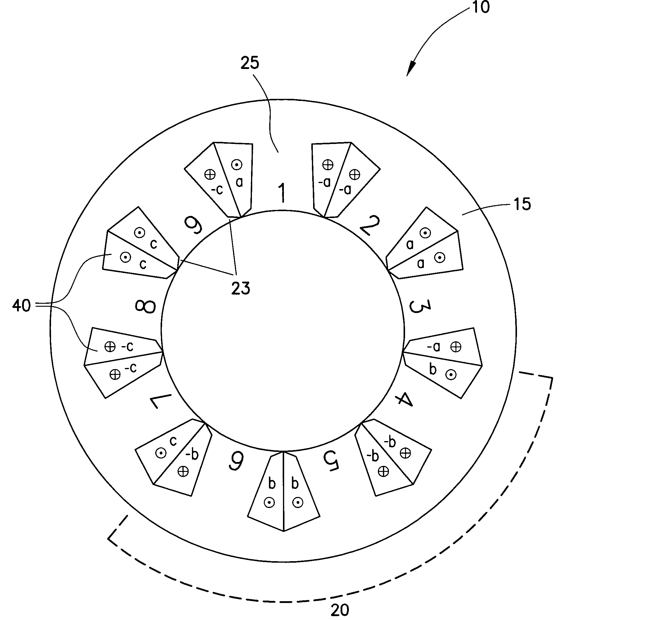
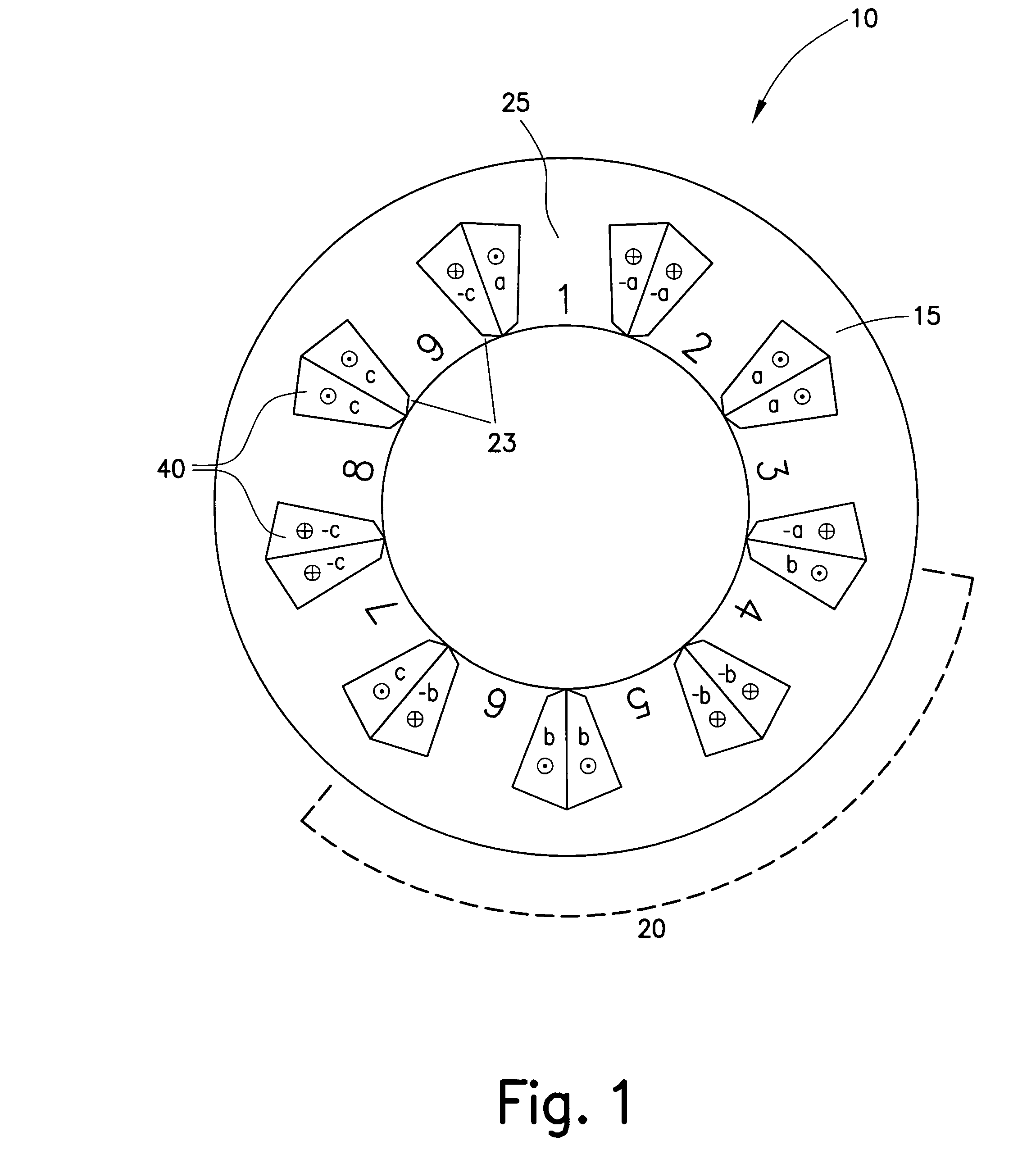
[0027] The following explanations relate especially to a synchronous motor, a rotor (secondary part) rotating within a stator (primary part). The exemplary embodiment and / or exemplary method of the present invention is meant also to include linear motors, asynchronous motors and also generators. Furthermore, the teeth responsible for the rotating field may point outwards, not as in the usual motors, where they point inwards, whereby either the stator of this motor lies inside, or the function of stator and rotor are exchanged. In the following, for rotary machines, the more usual expressions stator and rotor are used.

[0028]FIG. 1 shows a front view of a stator 10, according to the exemplary embodiment and / or exemplary method of the present invention, of an induction machine according to the exemplary embodiment and / or exemplary method of the present invention. In such a specific embodiment, stator 10 has 9 teeth 25, which are connected to one another via a yoke 15. Yoke 15 is cylin...


PUM


Abstract

A primary part of an electrical induction machine, especially a synchronous motor or a linear motor, includes a plurality of modules which each have teeth situated in a row having at least partially encircling slots, in the slot of each tooth a coil is wound around this tooth, and the coils of a single module are connected to a single phase of a rotary current network. The number of modules in the primary part is equal to the number of current phases or an integral multiple thereof. A single module includes an uneven number of teeth but at least three teeth, and teeth directly adjacent to one another of a single module include coils that have an opposite winding direction, which generates an opposite magnetic field polarity at the teeth. An electrical induction machine, especially a synchronous motor or a linear motor, includes a primary part and a secondary part, working together with the primary part via an air gap, which may have permanent magnets as rotor magnets.

Description

FIELD OF THE INVENTION [0001] The present invention relates to a primary part of an electrical induction machine and also an electrical induction machine, especially a synchronous motor or a linear motor for machines in which highly synchronous operation is required. BACKGROUND INFORMATION [0002] Such machines are used, for example, in printing machines and grinding machines. Furthermore, highly synchronous operation properties are necessary in servo applications. In order to achieve highly synchronous operation, so as, for instance, to be able to position exactly for servo applications, it is especially necessary for the motor to have a low torque ripple. Ideally, an electric motor should supply a constant torque at each point in time. Torque ripple is a measure of to what extent the torque of the motor deviates from the average torque of the motor at a point t. Most often, the torque ripple is stated with reference to the average torque of the electric motor as a function of the r...

Claims


Application Information

Patent Timeline
Patent Type & Authority Applications(United States)
IPC IPC(8): H02K17/00H02K3/00H02K1/10H02K1/26
CPCH02K3/28H02K21/16H02K29/03
Inventor GROENING, INGOLFKAEHLER, CHRISTIAN
Owner ROBERT BOSCH GMBH
Why Eureka
Try Eureka