Flexible display and manufacturing method thereof

a manufacturing method and display technology, applied in the field of flexible display, can solve the problems of difficult high-accuracy alignment, warping and expansion/contraction the possibility of heat distortion in manufacturing steps involving heat treatment, so as to achieve high yield and reduce manufacturing costs , the effect of improving reliability

Inactive Publication Date: 2006-06-22
KYODO INSATU KK KYODO PRINTING CO LTD +1
View PDF4 Cites 123 Cited by
  • Summary
  • Abstract
  • Description
  • Claims
  • Application Information

AI Technical Summary

Benefits of technology

[0028] In the flexible display of the present invention, as in the case of the invention described above, the organic active layer and the organic EL layer for

Problems solved by technology

However, since the plastic film has low rigidity and a low heat distortion temperature, heat distortion such as warping and expansion/contraction is likely to occur in manufacturing steps involving heat treatment.
Thus, in a manufacturing method by which various elements are formed directly on the plastic film, conditions of the manufacturing steps involving heat treatment are limited, and it becomes difficult to perform high-accuracy alignment.
Consequently, it may be impossible to manufacture an element substrate having desired characteristics.
A low-temperature polysilicon TFT or an amorphous silicon TFT as a conventional drive trans

Method used


Image

  • Flexible display and manufacturing method thereof
  • Flexible display and manufacturing method thereof
  • Flexible display and manufacturing method thereof

Examples


first embodiment

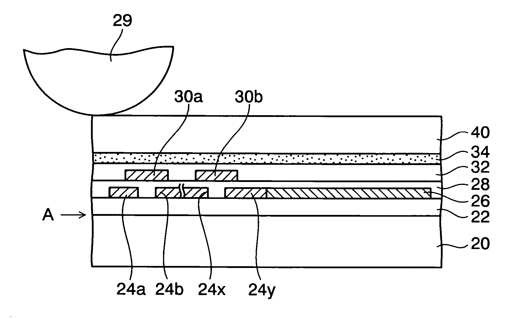
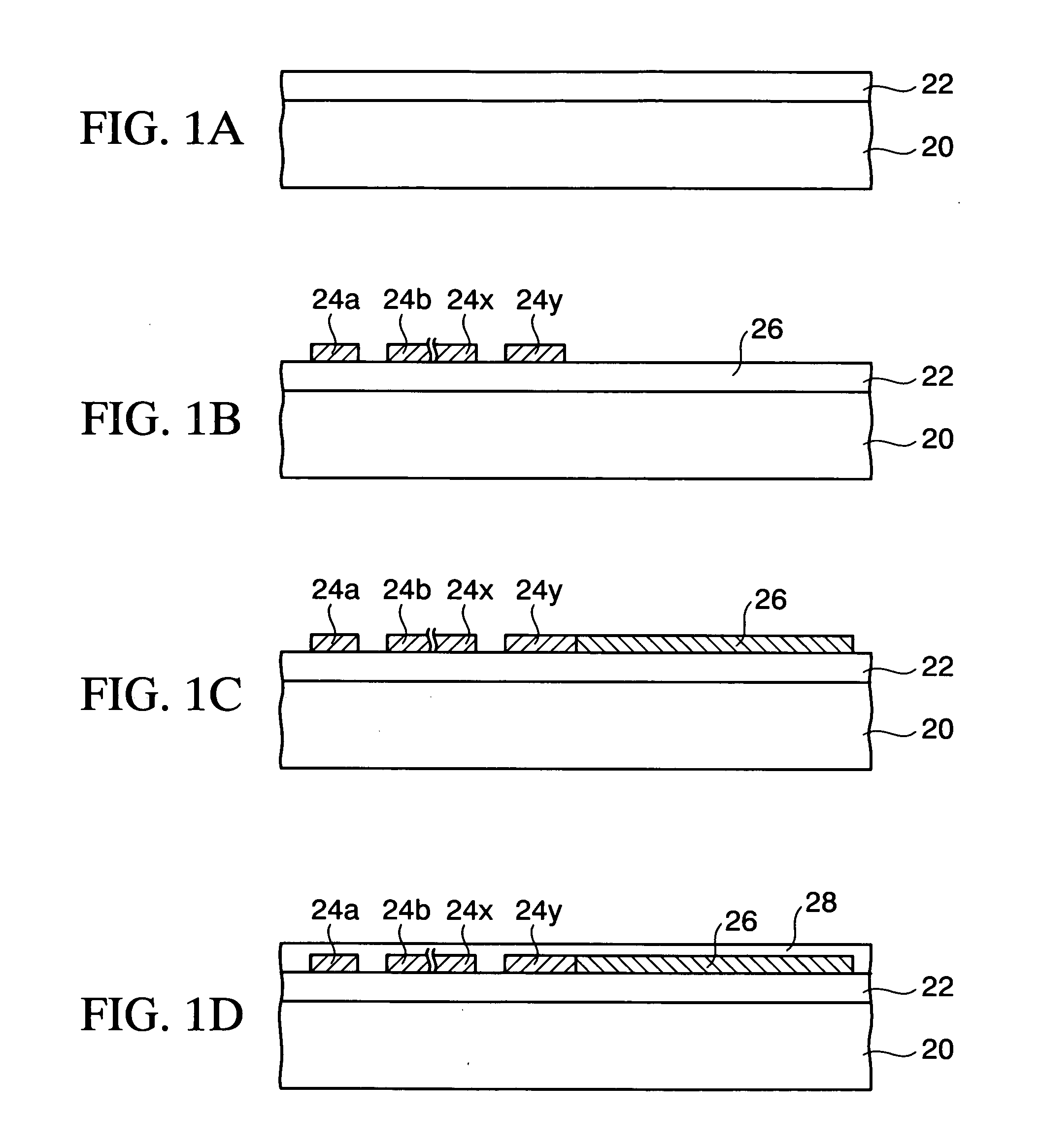
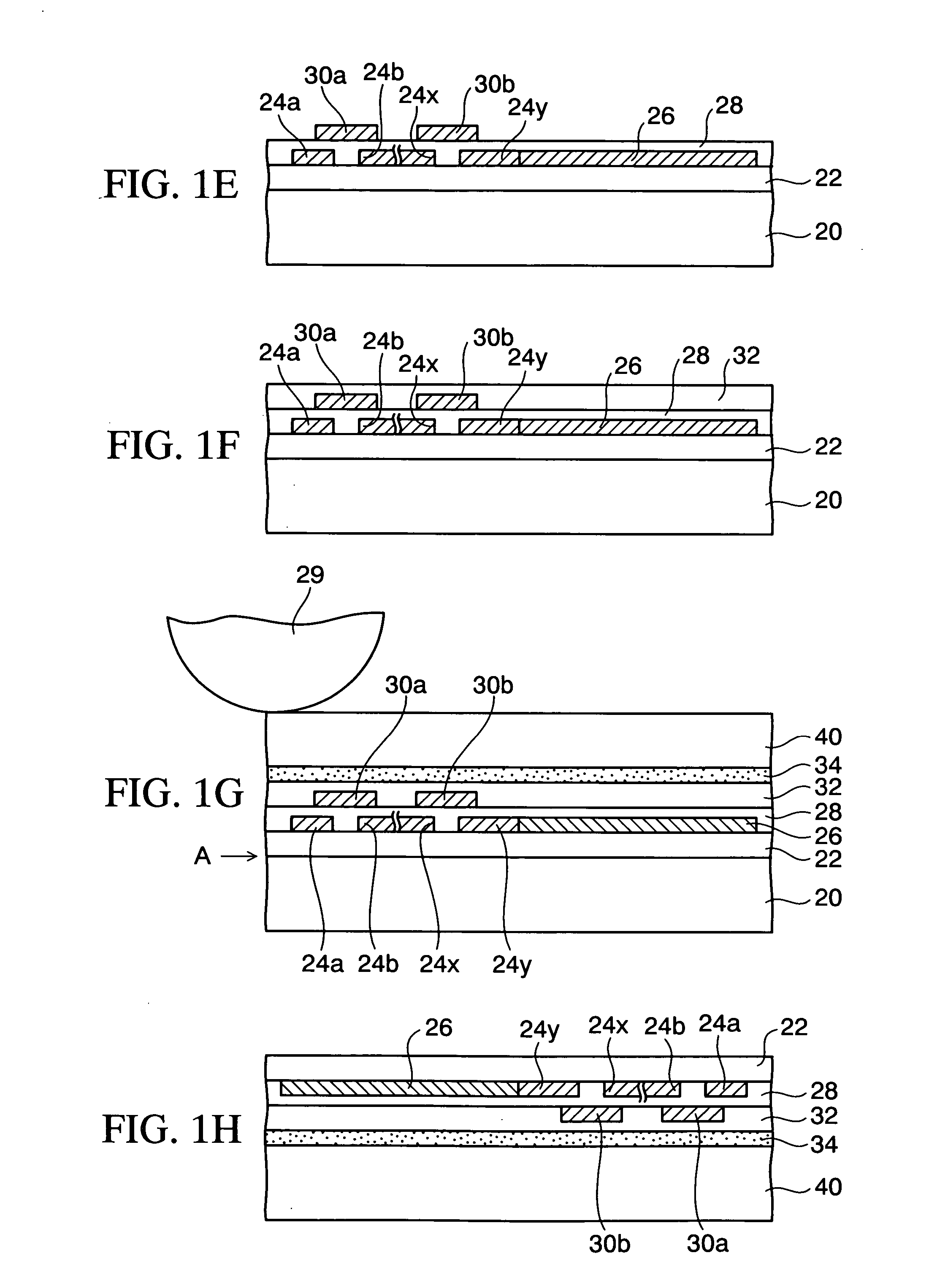
[0047]FIGS. 1A to 1M are cross-sectional views sequentially showing a method of manufacturing a flexible display according to a first embodiment of the present invention. FIG. 2 is a cross-sectional view showing a flexible display (an organic EL display) according to the first embodiment of the present invention. In the first embodiment, description will be given by taking the case of applying the present invention to the organic EL display as an example. In the method of manufacturing a flexible display according to the first embodiment of the present invention, as shown in FIG. 1A, first, a glass substrate 20 as a temporary substrate is prepared, and a peelable layer 22 made of a polyimide resin and the like is formed on the glass substrate 20.

[0048] Thereafter, as shown in FIG. 1B, a conductive layer made of gold (Au) having a thickness of, for example, 100 nm or the like is formed on the peelable layer 22. Subsequently, the conductive layer is patterned by photolithography and ...

second embodiment

[0091]FIG. 5 is a cross-sectional view showing a flexible display (an organic EL display) according to a second embodiment of the present invention. In the second embodiment, a full-color display is realized by using a white emitting layer as an emitting layer in an organic EL layer and combining color filter layers. In FIG. 5, the same components as those of the first embodiment shown in FIG. 2 are denoted by the same reference numerals, and description thereof will be omitted.

[0092] As shown in FIG. 5, a flexible organic EL display la of the second embodiment is formed by replacing all the red, green and blue layers 42R, 42G and 42B in the first embodiment shown in FIG. 2 with white emitting layers 42. Moreover, between a protective layer 32 and an adhesive layer 34, color filter layers 52R, 52G and 52B are formed in a state of being buried in the adhesive layer 34. The color filter layers include a red color filter layer 52R formed in a red pixel part (R), a green color filter l...

third embodiment

[0096]FIGS. 6A to 6K are cross-sectional views sequentially showing a method of manufacturing a flexible display according to a third embodiment of the present invention. In the first embodiment, the organic active layers and the organic EL layers for the TFTs are formed by the mask vapor deposition. Meanwhile, in the third embodiment, organic active layers and organic EL layers for TFTs are formed by an ink jet method or printing. In the third embodiment, detailed description of the same steps as those of the first embodiment will be omitted.

[0097] First, as shown in FIG. 6A, after a peelable layer 22 is formed on a glass substrate 20 as in the case of the first embodiment, a mask metal layer 25 having openings 25x provided in required portions is patterned on the peelable layer 22. As a material of the mask metal layer 25, aluminum (Al), silver (Ag) or the like is used. The openings 25x of the mask metal layer 25 are provided in portions corresponding to regions where organic act...


PUM


Abstract

A flexible display of the present invention is an active matrix flexible display in which a TFT is provided for each pixel. In the flexible display, an adhesive layer, a protective layer, a gate electrode for the TFT, which is buried in the protective layer, a gate insulating layer for the TFT, source and drain electrodes for the TFT, a pixel electrode electrically connected to the drain electrode, an organic active layer for the TFT, an organic EL layer including a red (R) emitting layer, a green (G) emitting layer and a blue (B) emitting layer, which are formed on a plurality of the pixel electrodes, a metal electrode, and a sealing layer are formed on a plastic film.

Description

BACKGROUND OF THE INVENTION [0001] 1. Field of the Invention [0002] The present invention relates to a flexible display and a manufacturing method thereof. More particularly, the present invention relates to a flexible display applicable to an organic EL display, a liquid crystal display and the like which use a plastic film as a substrate, and a manufacturing method thereof. [0003] 2. Description of the Related Art [0004] There has been a rapid increase in applications of a display device, such as an organic EL (electroluminescence) display and a liquid crystal display, to information device and the like. A flexible display using a plastic film as a substrate has recently attracted attention. Such a flexible display can be utilized not only for an ultraslim and light mobile device which can be housed while being rolled up and is easily carried around but also for a large-sized display. [0005] However, since the plastic film has low rigidity and a low heat distortion temperature, he...

Claims


Application Information

Patent Timeline
IPC IPC(8): G09G5/00
CPCG02F1/133305H01L27/322H01L27/3248H01L27/3274H01L51/0024H01L51/003H01L51/0097H01L51/56H01L2227/326H01L2251/5338Y02E10/549Y02P70/50H10K59/38H10K59/123H10K59/125H10K71/50H10K71/80H10K77/111H10K59/1201H10K71/00H10K2102/311
Inventor FURUKAWA, TADAHIROTOKITO, SHIZUOINOUE, YOUJISUZUKI, MITSUNORI
Owner KYODO INSATU KK KYODO PRINTING CO LTD
Why Eureka
Try Eureka