System and method for a thermogravimetric analyzer having improved dynamic weight baseline

a thermogravimetric analyzer and dynamic weight technology, applied in the direction of thermometer details, instruments, heat measurement, etc., can solve the problems of generating forces on the sample pan and associated components, and affecting the accuracy of the analysis. , to achieve the effect of eliminating weight errors

Active Publication Date: 2006-06-29
WATERS TECH CORP
View PDF22 Cites 18 Cited by
  • Summary
  • Abstract
  • Description
  • Claims
  • Application Information

AI Technical Summary

Benefits of technology

[0014] The thermocouple is part of a thermocouple assembly arranged in the cylinder. The thermocouple assembly includes a thermocouple attached to a disk that is substantially the same diameter as an inner diameter of the cylinder. In operation, the thermocouple assembly is arranged below the sample to limit convective flows around the sample, which could effect the weight measurement of the sample.
[0015] The TGA also includes a water-cooled plate between the balance chambe

Problems solved by technology

When attempting to make high sensitivity weight measurements a number of undesirable forces may act on the balance, sample, sample pan, and associated components of the weighing system.
For example, adsorption and desorption from the moving components of the balance may cause spurious weight changes.
Temperature fluctuations within the balance may cause weight changes due to thermal expansion of the balance arms or may affect the strength of the field developed by permanent magnets in electromagnetic drive systems so equipped.
Convection currents within the furnace or within the balance chamber may generate forces on the sample pan and associated components.
This particular problem may be especially severe when operating under vacuum.
Horizontal systems, however, generally have much heavier balance components that act to reduce

Method used


Image

  • System and method for a thermogravimetric analyzer having improved dynamic weight baseline
  • System and method for a thermogravimetric analyzer having improved dynamic weight baseline
  • System and method for a thermogravimetric analyzer having improved dynamic weight baseline

Examples


Embodiment Construction

[0027] The present invention relates to TGAs having an improved dynamic weight baseline. In a preferred embodiment of the present invention, the TGA configuration is vertical, with the balance mounted above the furnace. This preferred configuration provides the highest weight sensitivity.

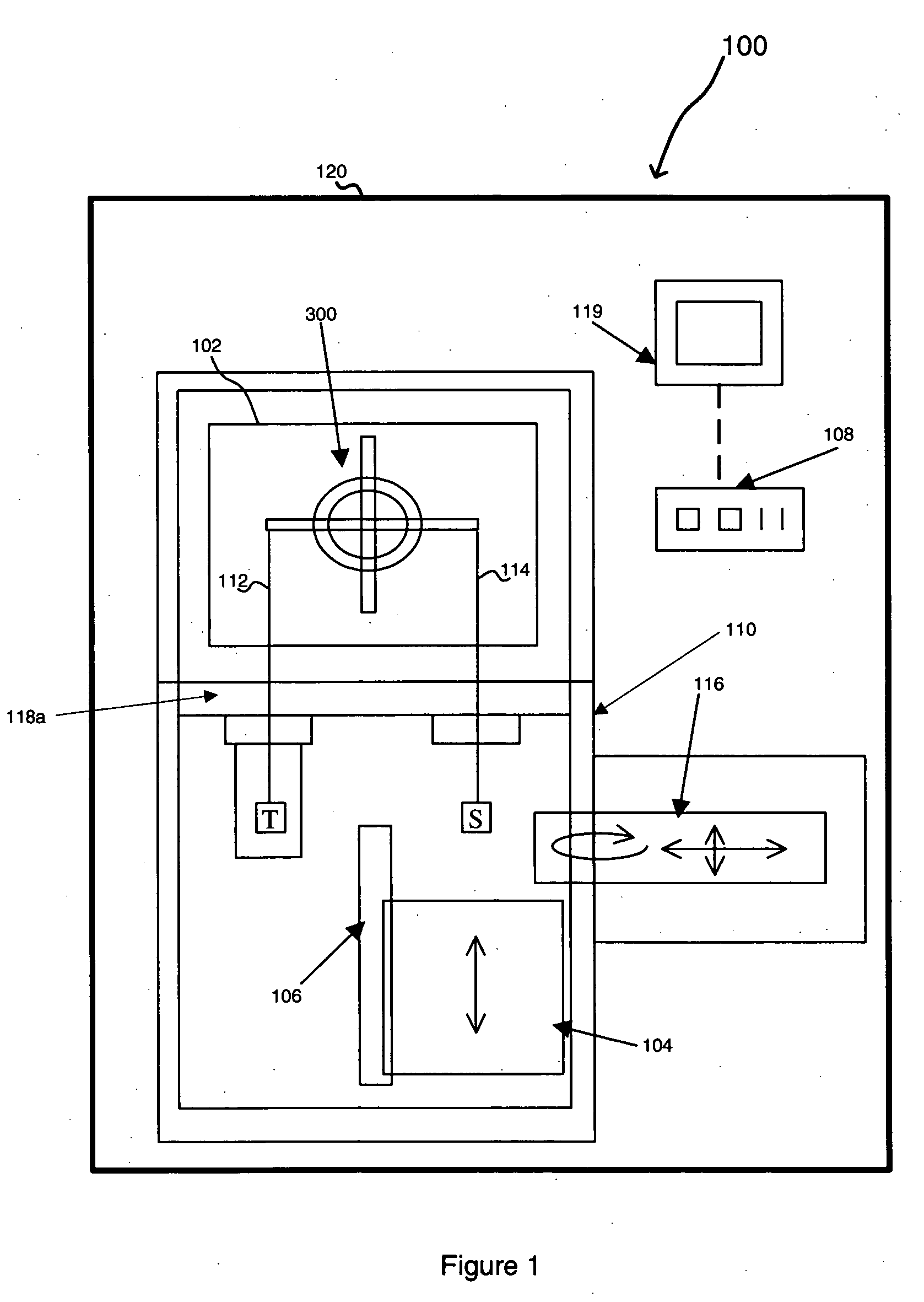
[0028]FIG. 1 is a schematic diagram of a TGA arranged in accordance with an exemplary embodiment of the present invention. TGA 100 includes a balance chamber 102, furnace 104, motorized linear actuator 106, electronic control unit 108, and TGA frame 110. Electronic control unit 108 may include a computer that controls the operation of TGA 100 and receives various measurements taken while TGA 100 is in use. For example, in one embodiment of the present invention control unit 108 controls furnace movement and heating, operation of autosampler 1116, and additionally manipulates measurement data taken to determine parameters such as sample temperature and sample weight, as described further below. In a...


PUM


Abstract

Systems and methods for minimizing extraneous forces and calculating corrected weights of samples based on buoyancy factors for a thermogravimetric analyzer (TGA). The TGA includes a balance chamber and a furnace configured to heat a sample. A null balance is provided in the balance chamber and is used to measure the sample weight change during heating. The furnace includes a cylinder open at the top to receive a sample. The bottom of the cylinder is closed except for a small hole that allows a thermocouple to pass through. An infrared heat source may be provided to heat the cylinder. The balance chamber can be thermally isolated from the furnace using an actively cooled plate and a system of heat shields disposed between the furnace and balance chamber. A thermocouple disk is further provided to limit gas flow in the furnace and increase reliability of sample weight measurements.

Description

[0001] This application claims priority to U.S. Provisional Application No. 60 / 639,301 filed Dec. 28, 2004 entitled System and Method for a Thermogravimetric Analyzer Having Improved Dynamic Weight Baseline.BACKGROUND [0002] 1. Field of the Invention [0003] The present invention relates generally to improving weight measurements of thermogravimetric analyzers. More particularly, the present invention relates to improving weight measurements for vertical thermogravimetric analyzers with a balance positioned above the furnace. [0004] 2. Background of the Invention [0005] Thermogravimetry is an analytical technique wherein a sample to be evaluated is subjected to a desired temperature program while its weight and temperature are measured. The weight change or the rate of weight change with respect to time or temperature may be displayed as a function of the measured temperature or of time and various evaluations may be performed. The weight curve versus temperature may be analyzed to d...

Claims


Application Information

Patent Timeline
IPC IPC(8): G01N25/00
CPCG01G19/52G01N5/04Y10S436/908G01N25/00
Inventor DANLEY, ROBERT L.SCHAEFER, JOHN W.
Owner WATERS TECH CORP
Why Eureka
Try Eureka