Vapor compression refrigerating device

a refrigerating device and vapor compression technology, applied in the direction of engine starters, machines/engines, lighting and heating apparatus, etc., can solve the problem of taking a certain time to reach the

Inactive Publication Date: 2006-07-06
DENSO CORP
View PDF3 Cites 34 Cited by
  • Summary
  • Abstract
  • Description
  • Claims
  • Application Information

AI Technical Summary

Benefits of technology

[0022] In the hybrid vehicle, an operation ratio of the engine is set at a lower value for a low speed running of the vehicle. An amount of the waste heat from the engine is therefore small

Problems solved by technology

However, it takes a certain time until the heating operation brings out its heating effect, because the heater core brings out its heating

Method used


Image

  • Vapor compression refrigerating device
  • Vapor compression refrigerating device
  • Vapor compression refrigerating device

Examples


first embodiment

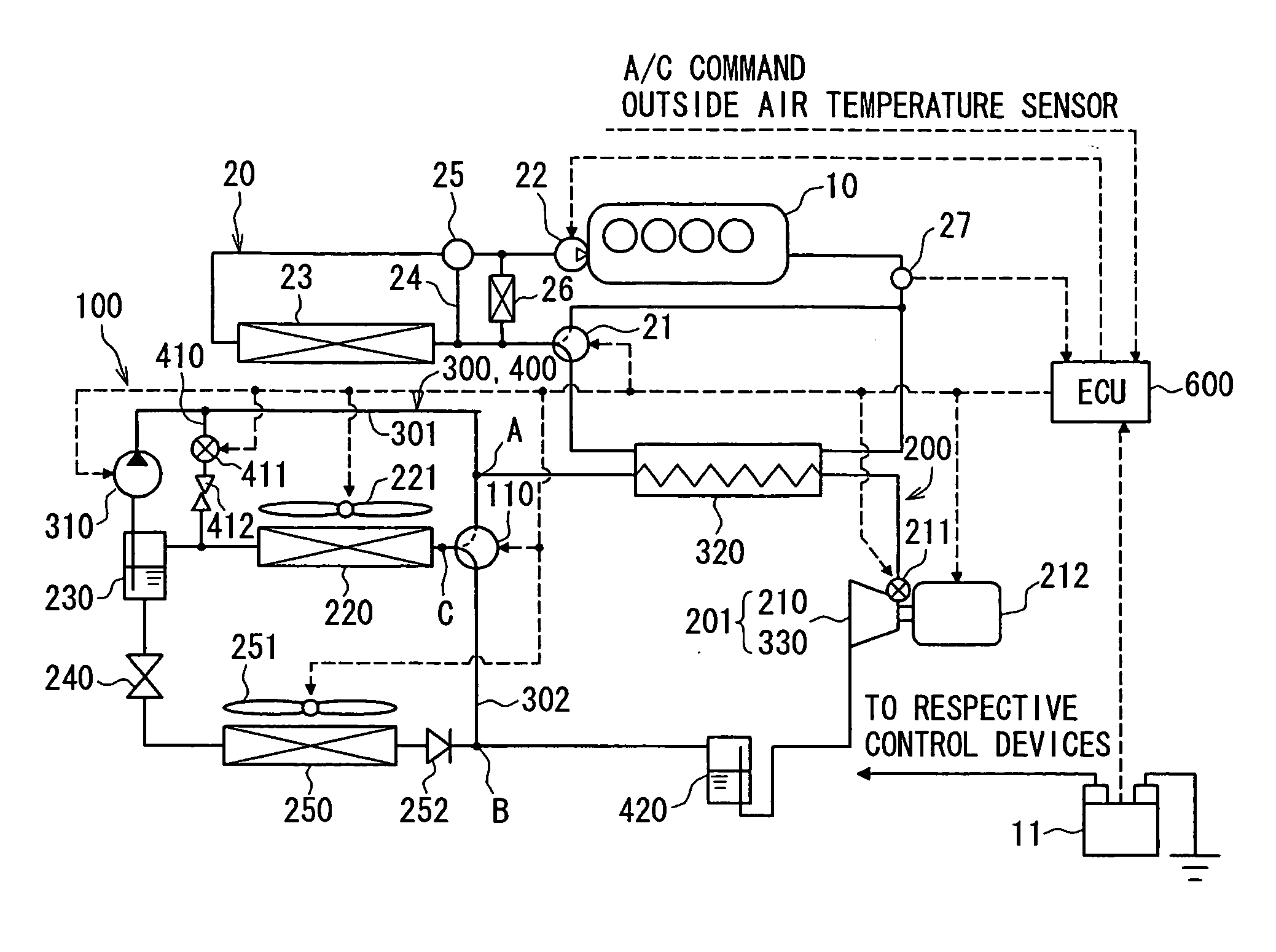
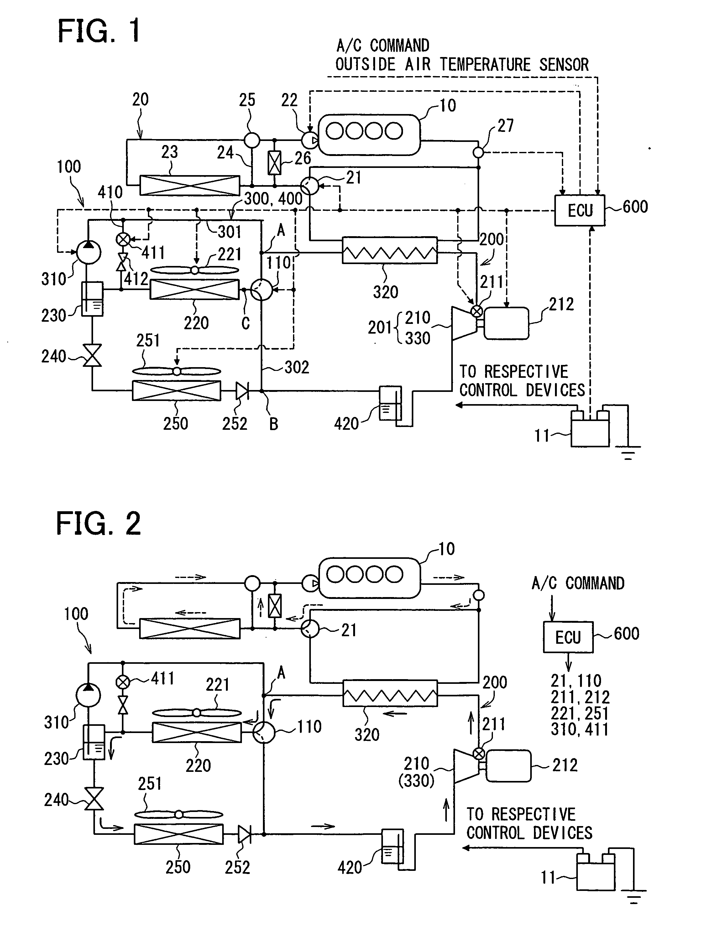
[0036]FIG. 1 shows a schematic system structure of a vapor compression refrigerating device 100 according to a first embodiment of the present invention, wherein the refrigerating device 100 is applied to an air conditioning system for a hybrid vehicle having a water cool type engine 10 and a motor for running, which are driving power sources for the vehicle.

[0037] As shown in FIG. 1, a Rankine cycle 300 and a heat pump cycle 400 as well as a well known refrigerating cycle 200 are incorporated in the vapor compression refrigerating device 100 (hereafter, simply referred to as the refrigerating device 100).

[0038] The refrigerating cycle 200 utilizes low temperature heat and high temperature heat by transferring heat from a low temperature side to a high temperature side, and includes a compressor device 210, a condenser device 220, a gas-liquid separator 230, a depressurizing device 240, and an evaporator 250, which are connected circularly in this order.

[0039] The compressor devi...

second embodiment

[0087] A second embodiment of the present invention is described with reference to FIGS. 10 to 12. The second embodiment is different from the first embodiment in that the heat pump cycle 400 is replaced with a hot gas cycle 500. More specifically, the liquid pump bypass passage 410, the ON-OFF valve 411 and the orifice 412 of the first embodiment are removed, and the hot gas cycle 500 is instead formed by commonly using the compressor device 210 and heating device 320 and by newly adding a switching passage 510.

[0088] The switching passage 510 is provided between a juncture D and a juncture E, wherein the juncture D is an intermediate point between the liquid pump 310 and the heating device 320 and the juncture E is an intermediate point between the switching valve 110 and the check valve 252. An ON / OFF valve 511 for opening and closing the switching passage 510 and an orifice 512 with a fixed opening degree are provided in the switching passage 510. The ON / OFF valve 511 is contro...


PUM


Abstract

In an automotive vehicle having a heater for a heating operation for a passenger room of the vehicle with use of waste heat of an engine, a vapor compression refrigerating device comprises a refrigerating cycle for a cooling operation for the passenger room. The vapor compression refrigerating device further comprises a heating cycle (a heat pump cycle, or a hot gas cycle) for performing a heating operation to engine cooling water by using the high temperature and high pressure refrigerant from a compressor device, wherein a control means activates the heating cycle at a predetermined time before starting an engine when an outside air temperature is lower than a predetermined value. Accordingly, the engine has been already warmed up before a driver gets into the vehicle.

Description

CROSS REFERENCE TO RELATED APPLICATION [0001] This application is based on and incorporates herein by reference Japanese patent application No. 2005-1922 filed on Jan. 6, 2005. FIELD OF THE INVENTION [0002] The present invention relates to a vapor compression refrigerating device having a heat pump cycle or a hot gas cycle, for which some of components of a refrigerating cycle are commonly used, and in particular relates to the vapor compression refrigerating device to be applied to an automotive air conditioning system. BACKGROUND OF THE INVENTION [0003] In a conventional automotive air conditioning system, as disclosed in Japanese Patent Publication No. 2001-301438, a heating operation is performed by a heat exchanger for heating (heater core), which is provided in a hot water circuit of an automotive engine and uses engine cooling water (hot water) as a heating source. In this system, a cooling operation is performed by an evaporator (corresponding to a heat exchanger for cooling...

Claims


Application Information

Patent Timeline
IPC IPC(8): F01K23/10F02N17/06B60H1/22F01N5/02F01P3/20F02G5/00F02G5/04F02N19/10F25B27/02
CPCF02N19/10F25B6/04F25B2339/047
Inventor INABA, ATSUSHIBAN, KOICHIYAMANAKA, YASUSHI
Owner DENSO CORP
Why Eureka
Try Eureka