Optical module and its wavelength monitor control method
a technology of optical modules and control methods, applied in the direction of optical radiation measurement, instruments, semiconductor lasers, etc., can solve the problems of difficult to reduce production costs, difficult to make the wavelength monitoring and controlling system small in size, and high cost of optical systems, so as to reduce power consumption and improve reliability in operation management, the effect of reducing the operation cos
- Summary
- Abstract
- Description
- Claims
- Application Information
AI Technical Summary
Benefits of technology
Problems solved by technology
Method used
Image
Examples
second embodiment
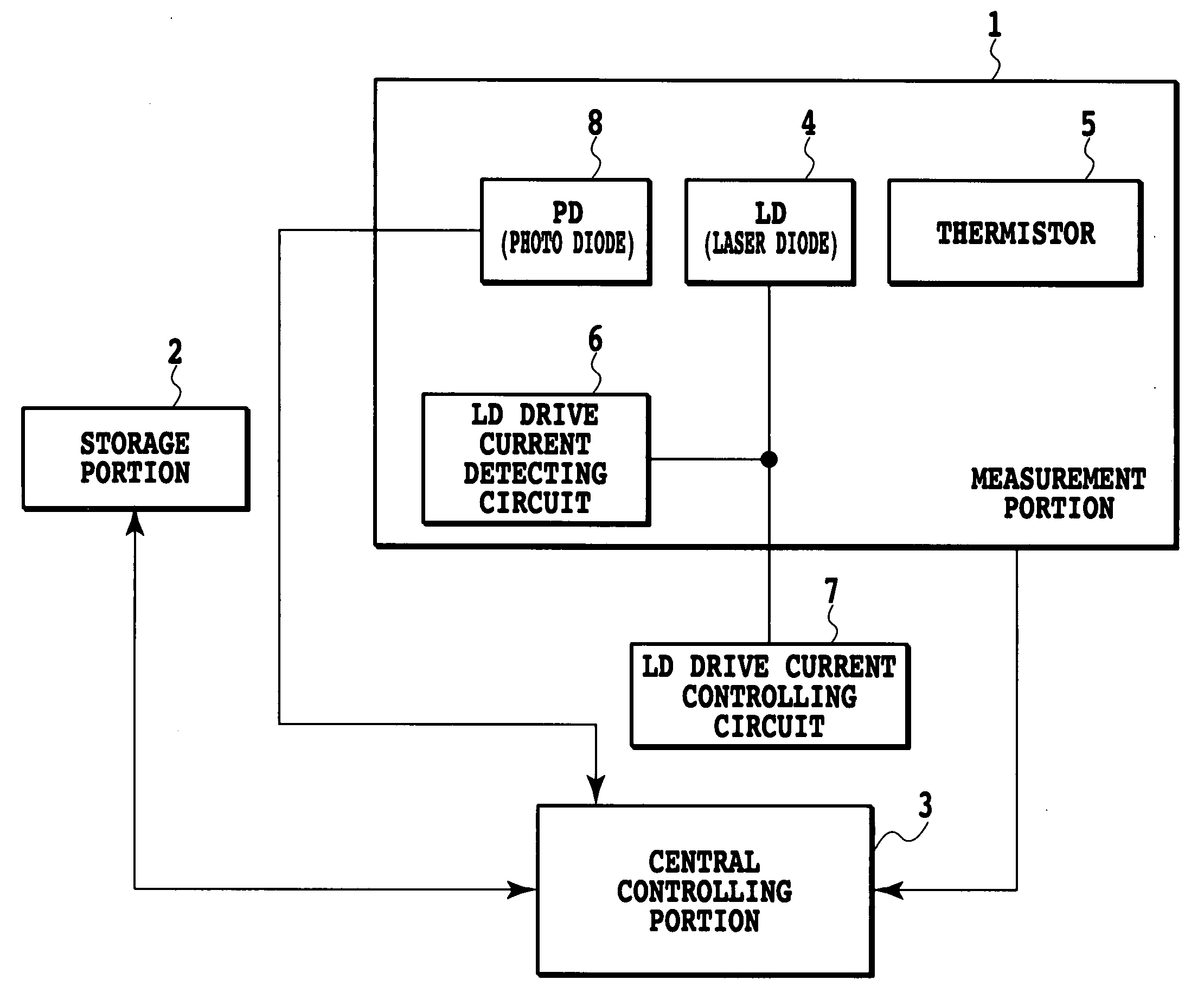
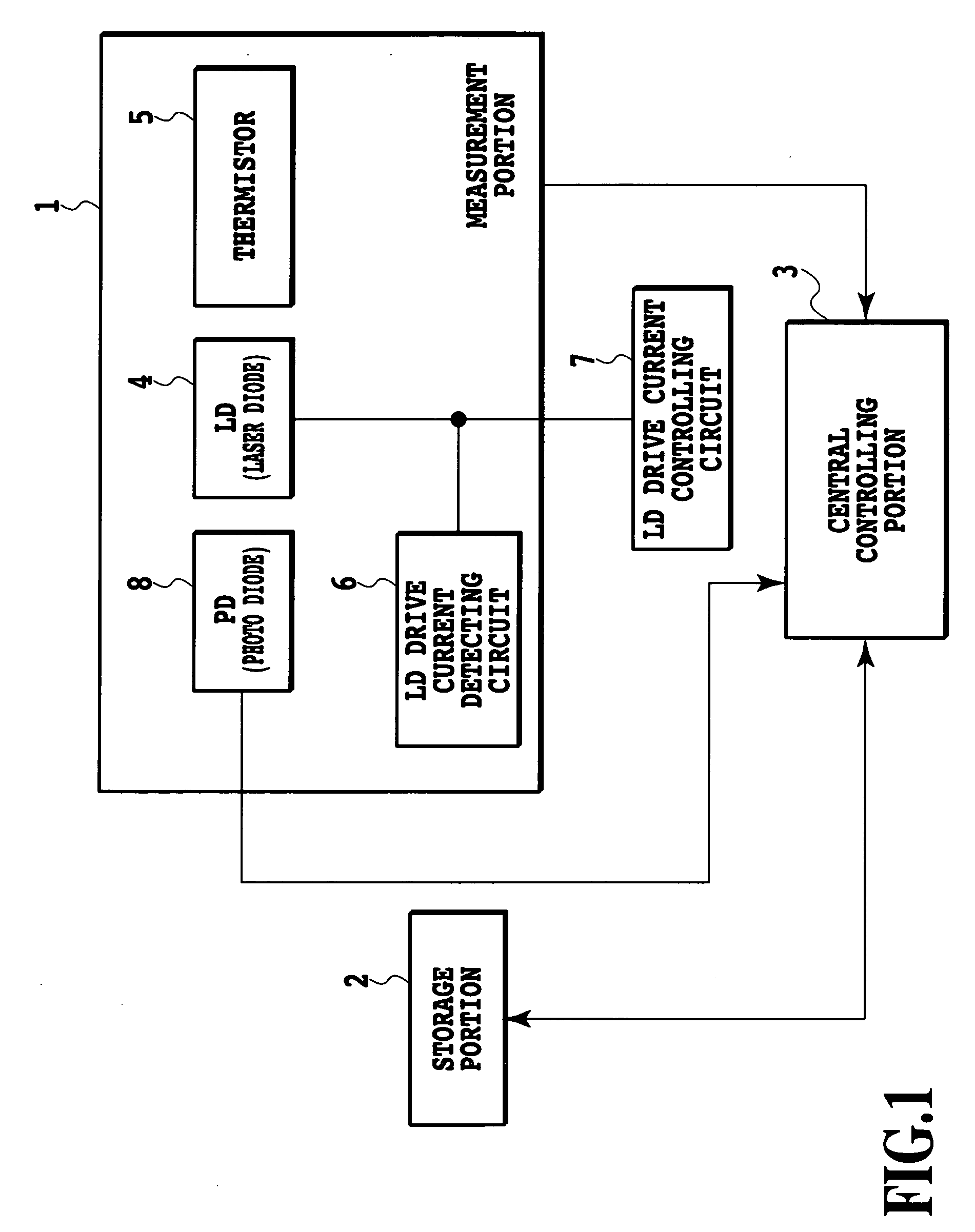
[0044] Next, a description is given of a wavelength monitoring method in an optical transmitter module or optical transmitter and receiver module according to the invention. By setting threshold values related to the wavelengths in the storage portion 2 and comparing the wavelengths calculated by the central controlling portion 3 with the threshold values, it becomes possible to issue an alarm or a warning with respect to wavelength deviation.
[0045] As a detailed example, a description is given of a Small Form Factor Pluggable (SFP) in which an optical portion of a device is formed of a pluggable small-type optical transmitter and receiver module. With respect to the SFP, the wavelength monitoring method is defined in SFP-8472 Revision 9.3 by the SFP Committee. A memory map held by the SFP is illustrated in FIG. 5.
[0046] Herein, threshold values for the alarm and warning are established in an area of 56 bytes in the Alarm and Warning Thresholds addresses 0 through 55 of the storage...
third embodiment
[0060] Next, a description is given of a wavelength monitoring and controlling method in an optical transmitter module or an optical transmitter and receiver module according to a
[0061]FIG. 8 is a flow chart showing a procedure to describe the wavelength monitoring and controlling method in an optical transmitter module or optical transmitter and receiver module according to the third embodiment. In detail, in the case of SFP, it is necessary to add a temperature adjusting portion.
[0062] First, the temperature, bias current and optical output are measured by the measurement portion 1 (S11). Next, by mapping (S12) in the Real Time Diagnostic Interface of the storage portion 2, the optical output is compared with the minimum threshold value of the optical output warning in the Alarm and Warning Thresholds of the storage portion 2 (S13). When the optical output is smaller than or equal to the minimum threshold value of the optical output warning, the Output Power LOW warning bit in th...
PUM
 Abstract
Description
Claims
Application Information
 - R&D
- Intellectual Property
- Life Sciences
- Materials
- Tech Scout
- Unparalleled Data Quality
- Higher Quality Content
- 60% Fewer Hallucinations
Browse by: Latest US Patents, China's latest patents, Technical Efficacy Thesaurus, Application Domain, Technology Topic, Popular Technical Reports.
© 2025 PatSnap. All rights reserved.Legal|Privacy policy|Modern Slavery Act Transparency Statement|Sitemap|About US| Contact US: help@patsnap.com


