Piezoelectric resonator and method for manufacturing the same

a technology of piezoelectric film and resonator, which is applied in the field of resonators, can solve the problems of difficult to keep the uppermost surface of the acoustic mirror flat, acoustic mirror is likely to warp, uneven thickness of piezoelectric film formed thereon,

Inactive Publication Date: 2006-07-06
PANASONIC CORP
View PDF4 Cites 20 Cited by
  • Summary
  • Abstract
  • Description
  • Claims
  • Application Information

AI Technical Summary

Benefits of technology

[0032] In the first method for manufacturing a piezoelectric resonator, it is preferred that the step (a) includes the step of forming a first barrier metal layer between the acoustic mirror and the first bottom electrode layer to prevent interdiffusion between the acoustic mirror and the bottom electrode. The first barrier metal layer is preferably made of nickel or platinum. As the above-described features prevent the interdiffusion from occurring between the bottom electrode and the acoustic mirror, changes in composition and structure of the bottom electrode and the acoustic mirror are surely a

Problems solved by technology

As the acoustic mirror is formed by alternately stacking the first acoustic mirror material layers and the second acoustic mirror material layers at least about 6 times, it is very difficult to keep the uppermost surface of the acoustic mirror flat.
Further, the acoustic mirror is likely to warp because the first and second acoustic mirror material layers have different thermal expansion coefficients.
If the bottom electrode is formed on the acoustic mirror which is not flat enough, the thickness of the piezoelectric film formed thereon becomes uneven.
Further, if the piezoelectric film is formed on the warped non-flat surface, the piezoelectric film deteriorates in crystallinity.
The poor crystallinity of the piezoelectric film indicates that there are many crystal defects and grain

Method used


Image

  • Piezoelectric resonator and method for manufacturing the same
  • Piezoelectric resonator and method for manufacturing the same
  • Piezoelectric resonator and method for manufacturing the same

Examples


first embodiment

Variant of First Embodiment

[0064]FIG. 3 shows a section of a variant of the piezoelectric resonator according to the first embodiment. In FIG. 3, the same components as those shown in FIG. 1 are indicated by the same reference numerals to omit the explanation.

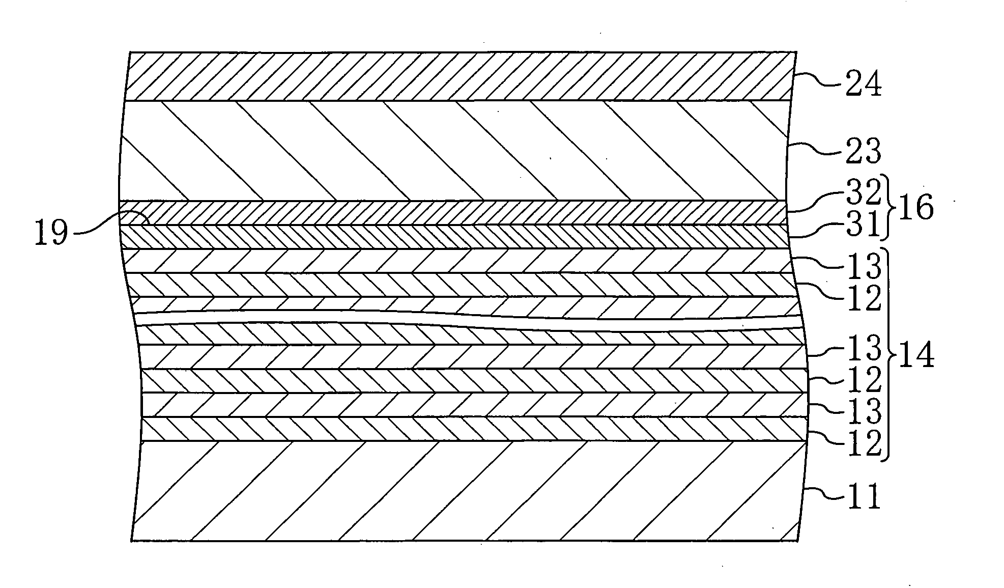
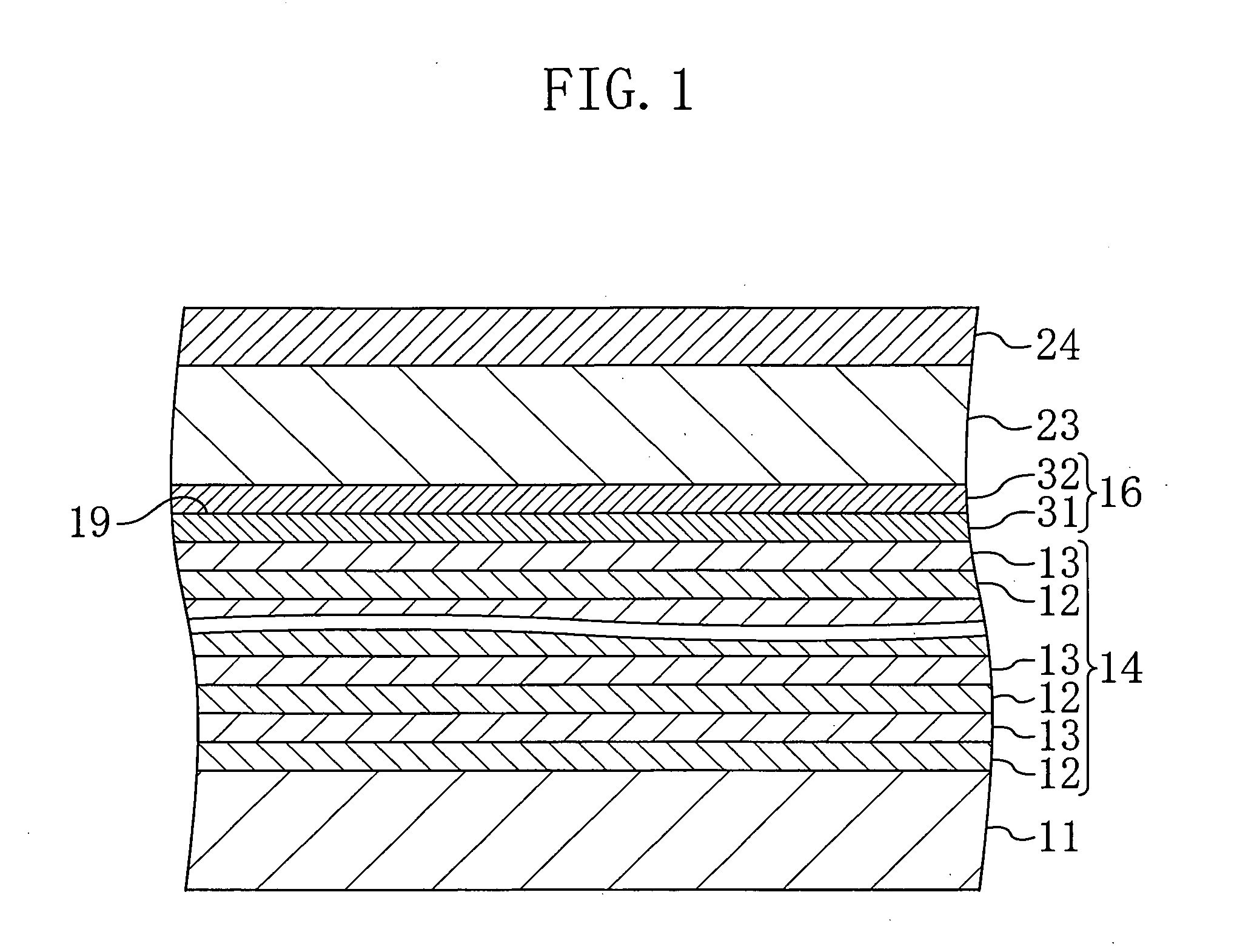
[0065] As shown in FIG. 3, a third adhesion layer 33 and a fourth adhesion layer 34, both of which are made of gold, are formed on a substrate 11. On the fourth adhesion layer 34, six first acoustic mirror material layers 12 made of SiO2 and six second acoustic mirror material layers 13 made of W are stacked alternately to form an acoustic mirror 14. A 300 nm thick bottom electrode 16 made of Mo is formed on the acoustic mirror 14. A piezoelectric film 23 made of AlN and a top electrode 24 made of Mo are formed on the bottom electrode 16.

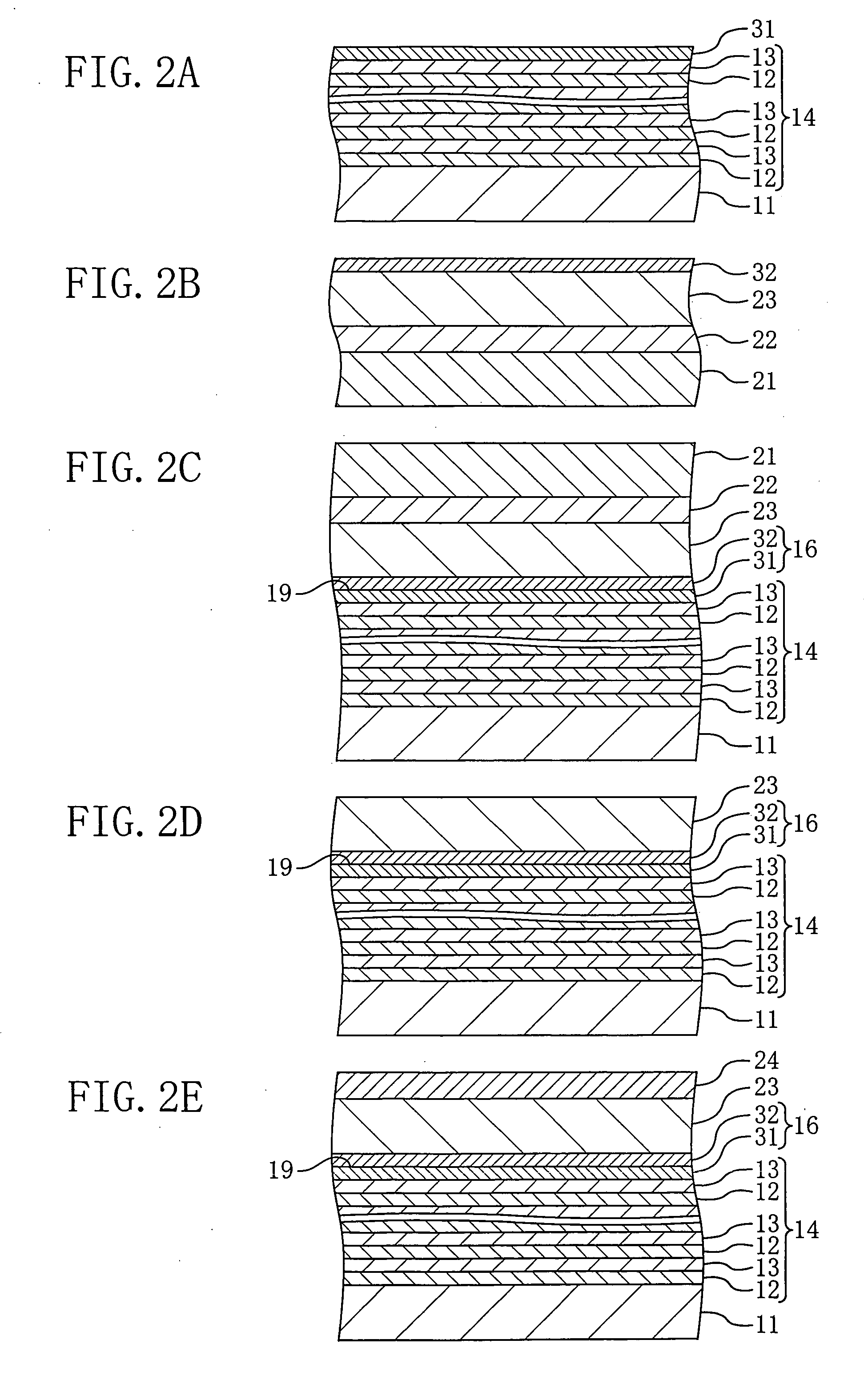
[0066]FIGS. 4A to 4D are sectional views illustrating the steps of manufacturing the variant of the piezoelectric resonator. As shown in FIG. 4A, first, a 150 nm thick Au layer is formed on t...

second embodiment

[0071] Hereinafter, an explanation of a piezoelectric resonator according to the second embodiment of the present invention will be provided with reference to the figures. FIG. 5 is a sectional view illustrating the structure of the piezoelectric resonator of the present embodiment. In FIG. 5, the same components as those shown in FIG. 1 are indicated by the same reference numerals to omit the explanation.

[0072] As shown in FIG. 5, a top acoustic mirror 15 is formed on the top electrode 24 of the piezoelectric resonator of the first embodiment. Specifically, the top electrode 24 formed on the piezoelectric film 23 includes a fifth adhesion layer 35 and a sixth adhesion layer 36, both of which are 150 nm in thickness and made of Au. The fifth and sixth adhesion layers 35 and 36 form a bonding interface 35 therebetween. The top acoustic mirror 15 on the top electrode 24 is formed by alternately stacking six first acoustic mirror material layers 12 and six second acoustic mirror mater...

third embodiment

Variant of Third Embodiment

[0089]FIG. 8 illustrates a section of a variant of the piezoelectric resonator according to the third embodiment. In FIG. 8, the same components as those shown in FIG. 7 are indicated by the same reference numerals to omit the explanation.

[0090] As shown in FIG. 8, in the variant of the third embodiment, a barrier metal layer 52 is formed on the top electrode 24 and a top acoustic mirror 15 is formed on the barrier metal layer 52.

[0091] Therefore, interdiffusion is prevented from occurring between the top electrode 24 and the first acoustic mirror material layer of the top acoustic mirror 15.

[0092] As described above, the piezoelectric resonator and the method for manufacturing the same according to the present invention make it possible to use a piezoelectric film with high crystallinity and excellent flatness in a piezoelectric resonator including an acoustic mirror. As the present invention achieves a piezoelectric resonator with less insertion loss ...


PUM


Abstract

A piezoelectric resonator includes a substrate, an acoustic mirror formed on the substrate and includes alternately stacked first acoustic mirror material layers and second acoustic mirror material layers having higher acoustic impedance than that of the first acoustic mirror material layers, a piezoelectric film formed on the acoustic mirror, a top electrode formed on the piezoelectric film and a bottom electrode formed below the piezoelectric film. A bonding interface is provided between metal films bonded to each other between the substrate and the piezoelectric film.

Description

CROSS-REFERENCE TO RELATED APPLICATION [0001] This non-provisional application claims priority under 35 U.S.C. §119(a) of Japanese Patent Application No. 2005-853 filed in Japan on Jan. 5, 2005, the entire contents of which are hereby incorporated by reference. BACKGROUND OF THE INVENTION [0002] 1. Field of the Invention [0003] The present invention relates to a resonator which is applicable to a high frequency filter in an electronic circuit, particularly to an acoustic resonator which makes use of the resonance of a piezoelectric substance. [0004] 2. Description of Related Art [0005] According to global dissemination of cellular phones in recent years, a small-sized, high performance filter has been demanded. A resonator is one of the components of the filter. Aiming at size reduction and improvement in performance of the filter, attempts have been made to the manufacture of a filter including a SAW resonator using surface acoustic waves or a piezoelectric resonator using bulk aco...

Claims


Application Information

Patent Timeline
IPC IPC(8): H03H9/54H01L41/09H01L41/18H01L41/187H01L41/22H01L41/29H01L41/313H03H3/02H03H9/17
CPCH03H3/02H03H9/02094H03H9/02149H03H9/175
Inventor ISHII, MOTONORIYAHATA, KAZUHIROTSURUMI, NAOHIRO
Owner PANASONIC CORP
Why Eureka
Try Eureka