Picture element structure of current programming method type active matrix organic emitting diode display and driving method of data line
a technology of active matrix and driving method, which is applied in the direction of instruments, static indicating devices, etc., can solve the problems of deviation in oled output current, difficulty in manufacturing an ltps tft with such a desired uniformity, etc., and achieve the effect of increasing the output resistance of the fourth driving transistor
- Summary
- Abstract
- Description
- Claims
- Application Information
AI Technical Summary
Benefits of technology
Problems solved by technology
Method used
Image
Examples
first embodiment
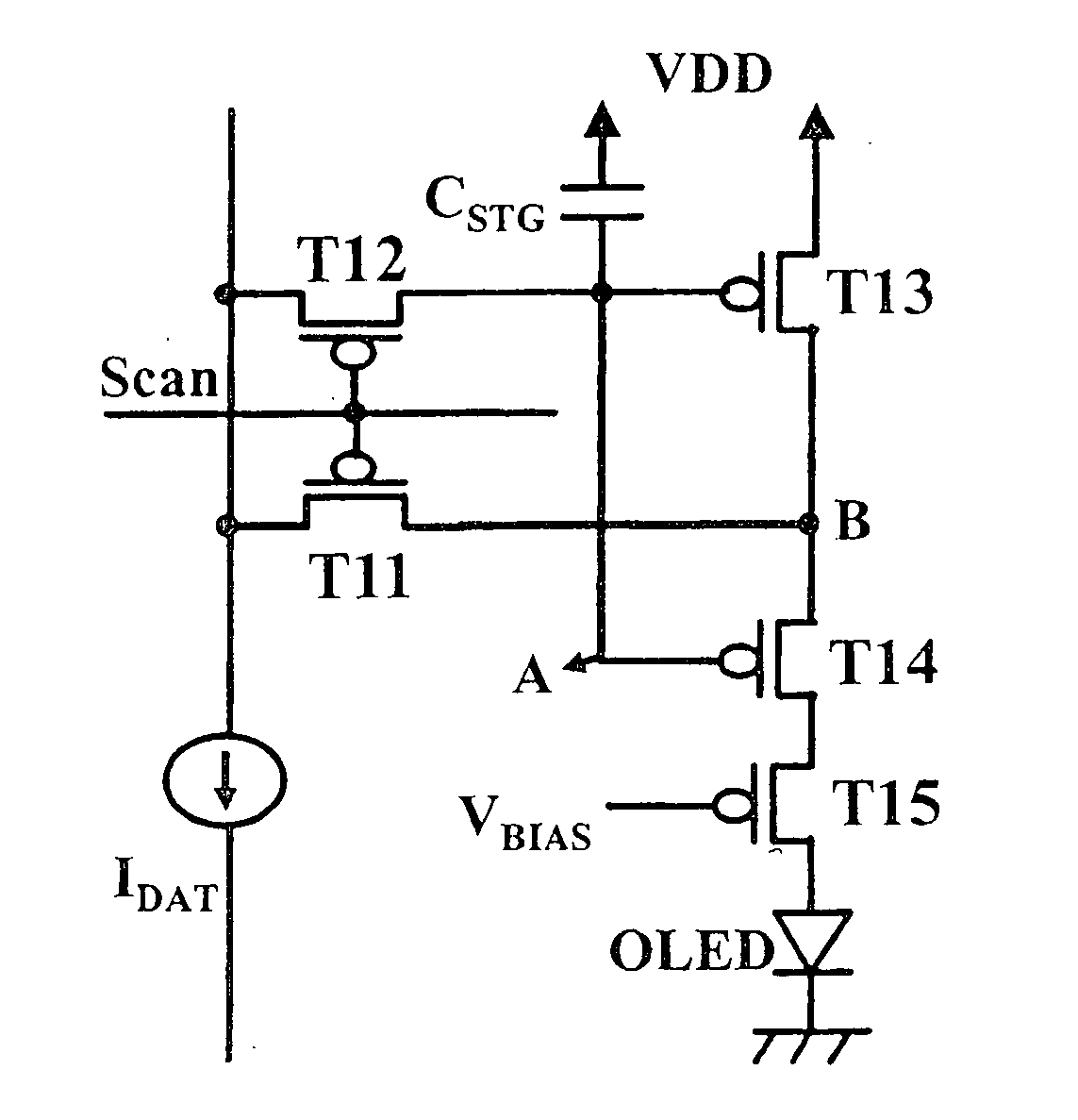
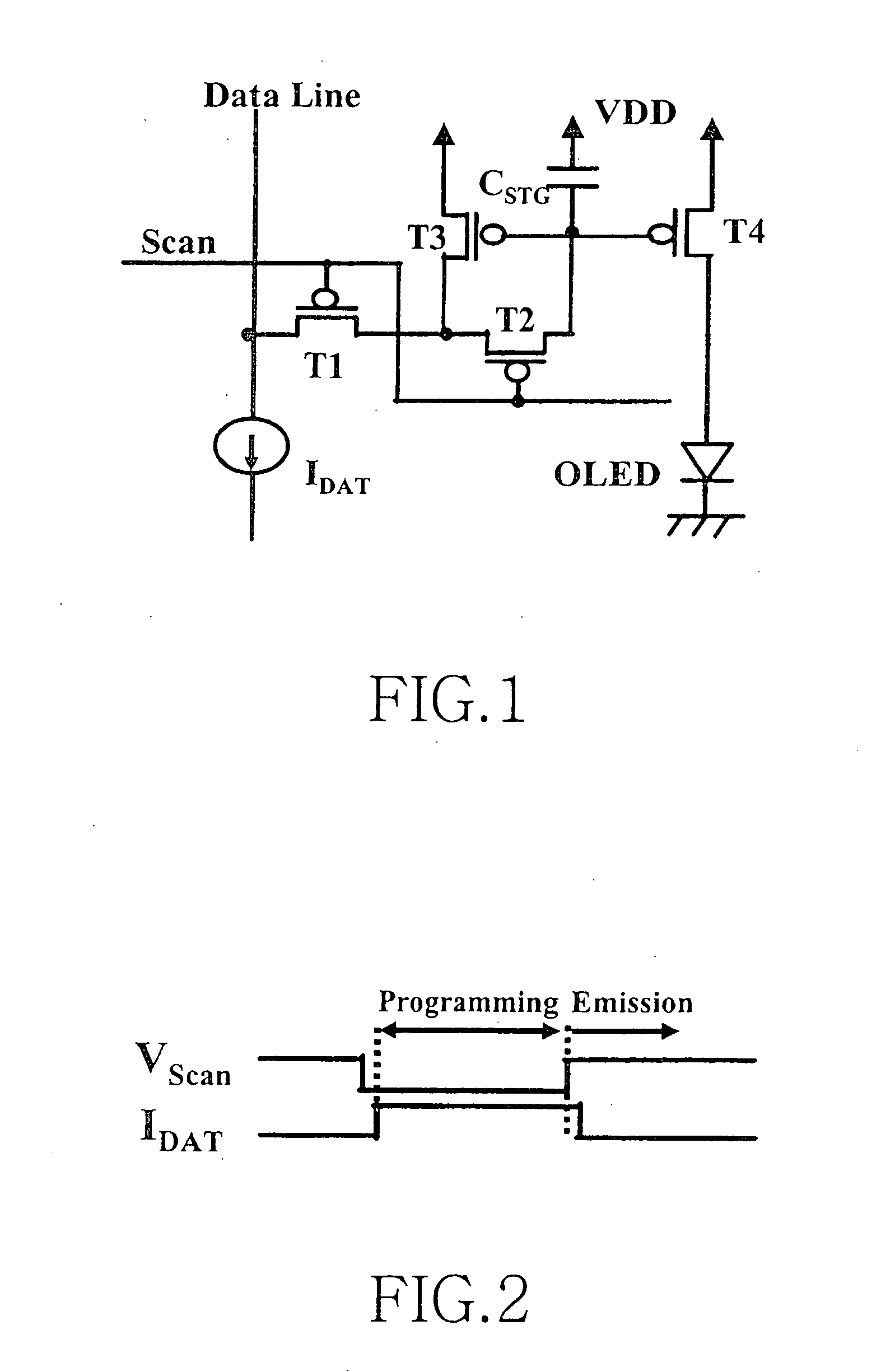
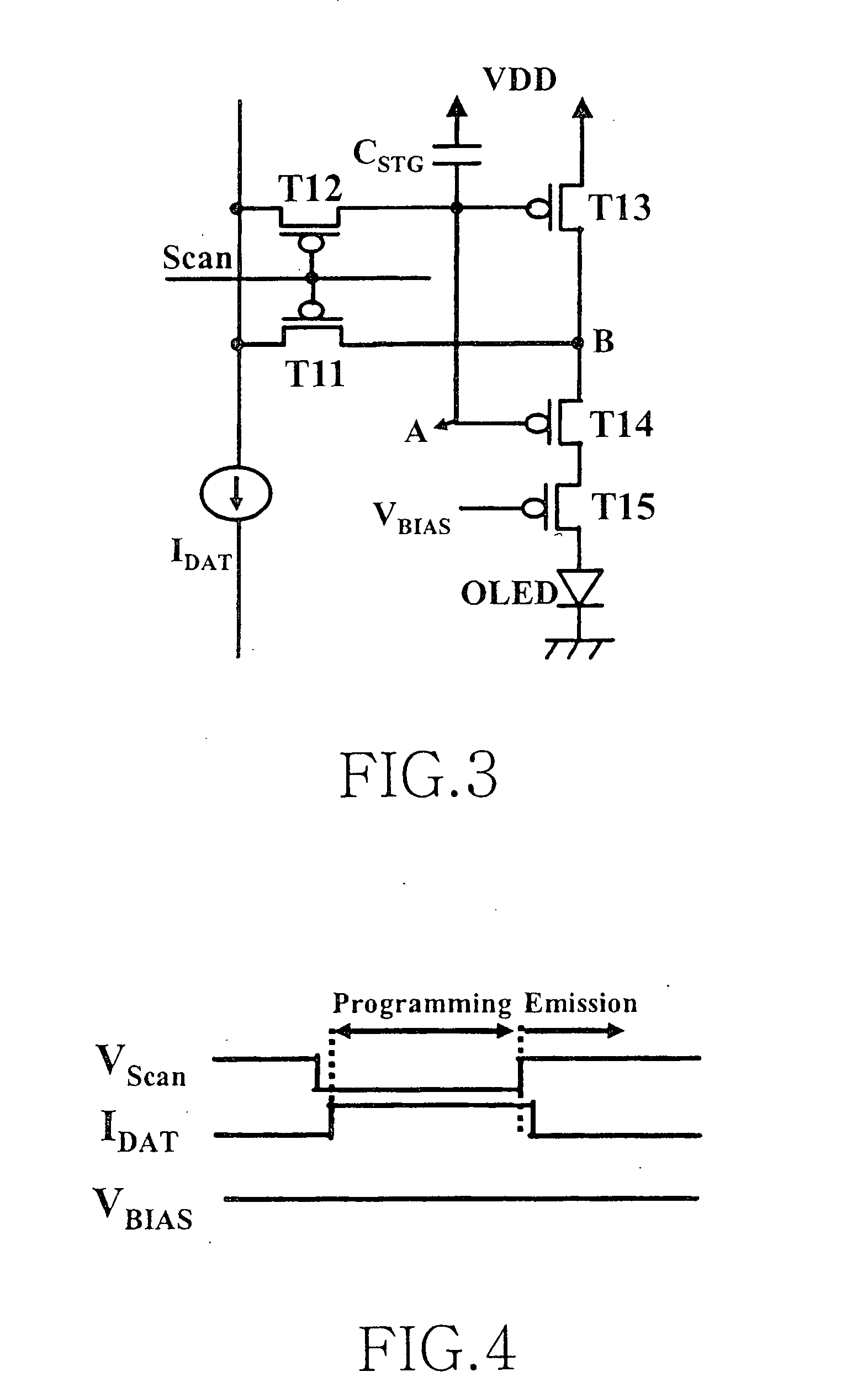
[0043]FIG. 3 schematically shows the structure of picture element in a current programming type of active matrix OLED according to the present invention, and then FIG. 4 shows a timing diagram of operation in FIG. 3. Referring now to FIG. 3, it is seen that the picture element in a current programming type of active matrix OLED according to the preferred embodiment of the present invention is configured to have five P-type thin film transistors (TFTs) T11 to T15 and a capacitor CSTG, in such a manner that a DC signal VBIAS in addition to a scan signal and a data signal IDATA, which are essential signals for the picture element, is further applied to a gate of TFT T15. It should be appreciated that this embodiment as described above also utilizes a characteristic that threshold voltages and field effect mobility in TFT T13 and TFT T14 are substantially identical to each other, as is with the current-mirror structure indicated in the known structure of FIG. 1. In a low temperature pol...
fourth embodiment
[0059]FIG. 11 schematically shows the picture element structure in a current programming type of active matrix OLED according to the present invention, and
[0060]FIG. 12 shows a timing diagram of operation in FIG. 11. As seen in FIG. 11, the picture element in a current programming type of active matrix OLED according to this embodiment includes five P-type TFTs T41 to T45 and a capacitor CSTG, as seen in the first embodiment of FIG. 3. Here, the difference in structure between this embodiment and the first embodiment of FIG. 3 is that two scan signals are applied to effect more stable circuit operation, so that TFT T41 is turned OFF earlier than TFT T42 in operation. This inventive idea of controlling a switching of two TFTs T41 and T42 using these two scan signals may be likewise applied to all the aforementioned embodiments of the present invention and any other alternative embodiments to be discussed in the following.
[0061]FIG. 13 schematically shows the picture element structur...
third embodiment
[0063] The basic concept that was applied to the preferred embodiments of FIGS. 13 and 15, for outputting the compensated OLED current by changing the physical position of TFT T2, may be also utilized for FIG. 9 according to the present invention.
PUM
 Abstract
Description
Claims
Application Information
 - R&D
- Intellectual Property
- Life Sciences
- Materials
- Tech Scout
- Unparalleled Data Quality
- Higher Quality Content
- 60% Fewer Hallucinations
Browse by: Latest US Patents, China's latest patents, Technical Efficacy Thesaurus, Application Domain, Technology Topic, Popular Technical Reports.
© 2025 PatSnap. All rights reserved.Legal|Privacy policy|Modern Slavery Act Transparency Statement|Sitemap|About US| Contact US: help@patsnap.com


