Electrophotographic photoreceptor and charge-transporting material for electrophotographic photoreceptor
- Summary
- Abstract
- Description
- Claims
- Application Information
AI Technical Summary
Benefits of technology
Problems solved by technology
Method used
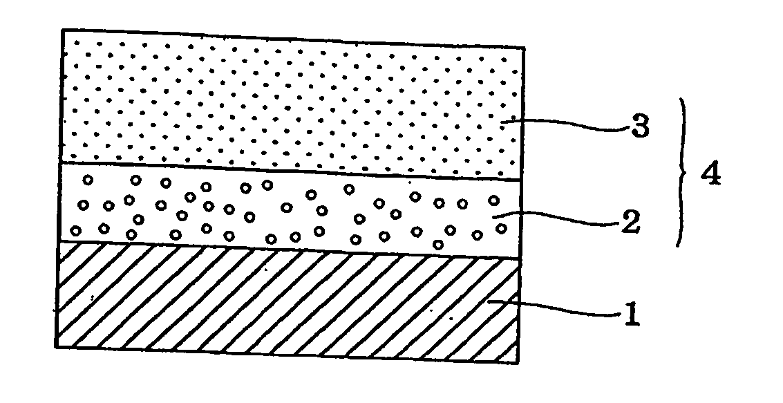
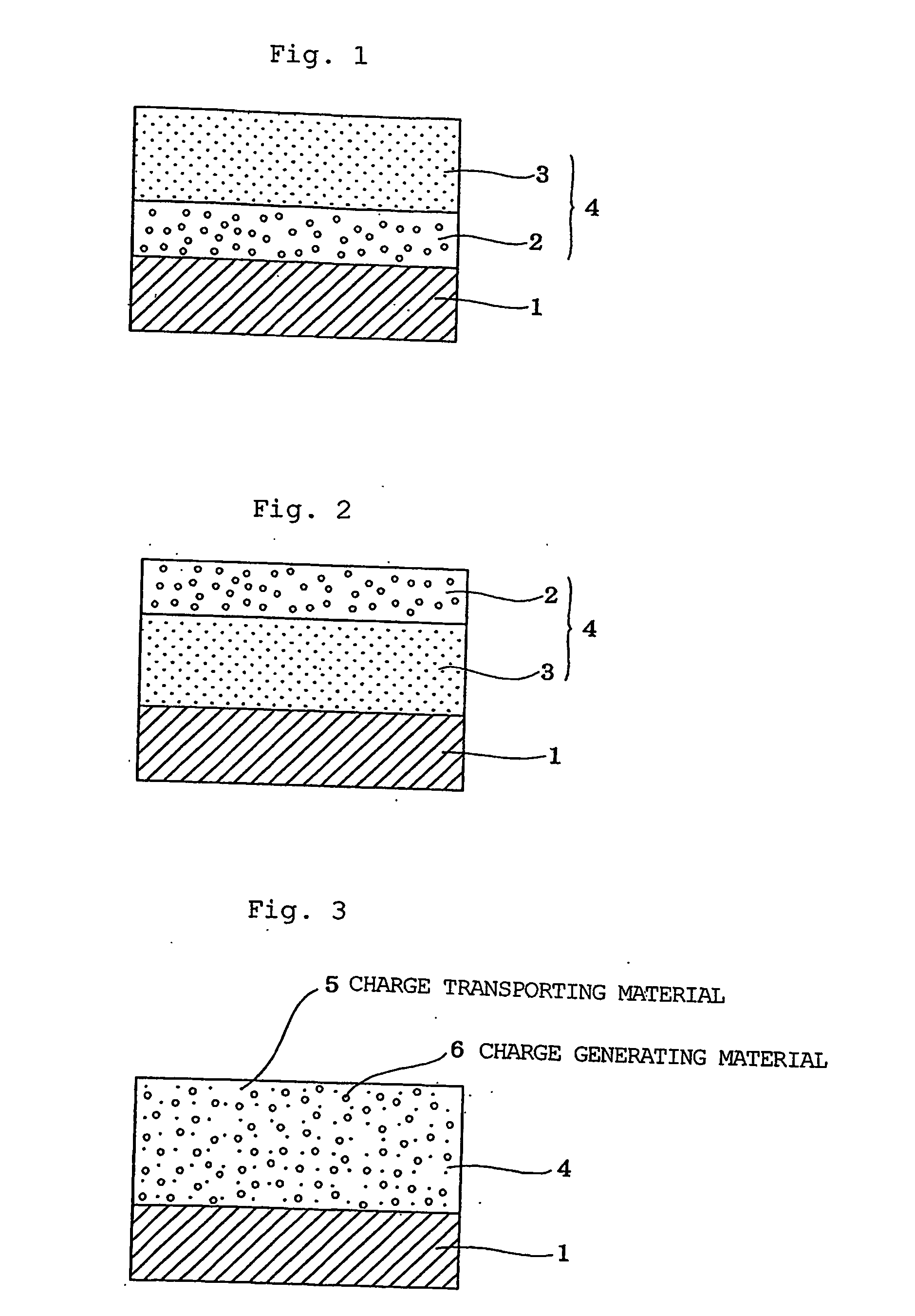
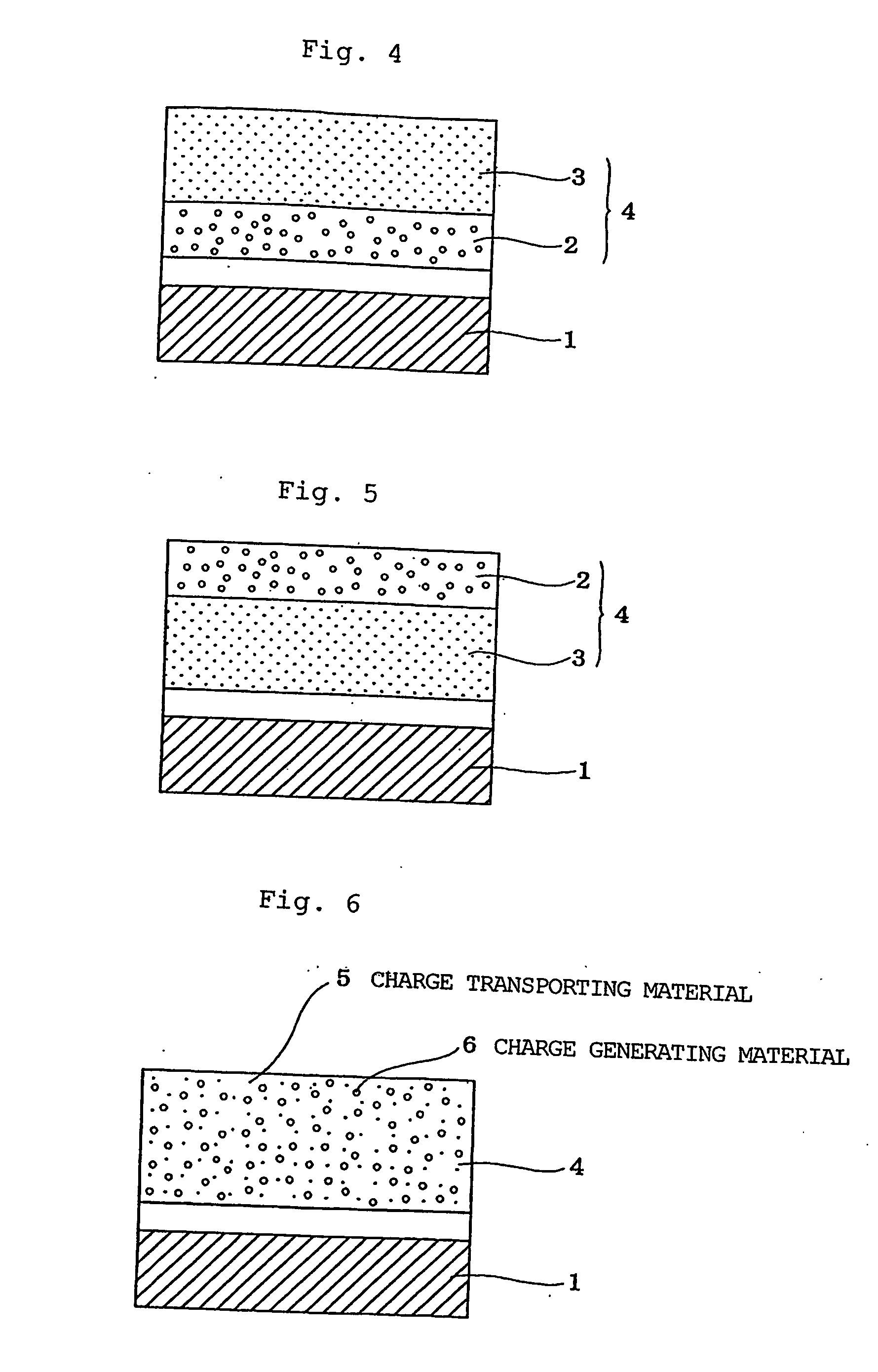
Image

Examples
synthesis example 1
Synthesis of Compound 1-1 [Compound of the Formula (1) Wherein R1 to R5═H and R6═H]
(1) Synthesis of 4-bromostilbene [4a; compound of the formula (4) in the synthesis scheme 1 wherein R1 to R5═H, R6═H and X═Br]
[0072] 18 g (0.16 mol) of potassium tert-butoxide was gradually added at 30 to 50° C. to a solution of 15.8 g (0.149 mol) of benzaldehyde and 40.6 g (0.132 mol) of diethyl p-bromobenzylphosphite in 60 ml of N,N-dimethylformamide. Further, 40 ml of N,N-dimethylformamide was added thereto, and the solution was stirred at room temperature for 2 hours to react. The reaction solution was poured into water, extracted with butyl acetate and, after washing twice with water, the extract was dried over magnesium sulfate and concentrated to obtain 33.9 g of crude crystals. Recrystallization of the thus obtained crude crystals from toluene-isopropanol (hereinafter abbreviated as “IPA”) yielded 29.0 g of an end product. Yield: 84.8%; mp: 131-133° C.
[0073]1H-NMR: 7.07 (ABq, d=16.3 Hz, 2H),...
synthesis example 2
Synthesis of Compound 1-2 [Compound of the Formula (1) Wherein R′ or R5=Me and R6═H]
(1) Synthesis of 4-bromo-2′-methylstilbene [4b; compound of the formula (4) in the synthesis scheme 1 wherein R1=Me, R2 to R5═H, R6═H, and X═Br]
[0078] A mixed solution of 23 g (0.124 mol) of p-bromobenzaldehyde [5a; compound of the formula (5) in the synthesis scheme 1 wherein X═Br; hereinafter the same] and 33 g (0.136 mol) of diethyl o-methylbenzylphosphite [6a; compound of the formula (6) in the synthesis scheme 1 wherein R1=Me, R2 to R5═H, R6═H, and R7=Et] in 70 ml of N,N-dimethylformamide was gradually added to a suspension of 5.7 g (0.143 mol) of 60% sodium hydride in 30 ml of N,N-dimethylformamide at 20 to 30° C. After stirring the mixture for 1 hour at room temperature to react, the reaction solution was poured into water, extracted with toluene and, after washing with water, the extract was dried over magnesium sulfate and concentrated to obtain 36.99 g of crude crystals. Recrystallization ...
synthesis example 3
Synthesis of Compound 1-3 [Compound of the Formula (1) Wherein R2 or R4=Me, R1 to R5 Other than R2 or R4═H, and R6═H]
(1) Synthesis of 4-bromo-3′-methylstilbene [4c; compound of the formula (4) in the synthesis scheme 1 wherein R2 or R4=Me, R1 to R5 other than R2 or R4═H, R6═H, and X═Br]
[0085] 8.5 g (0.213 mol) of 60% sodium hydride, 35 g (0.189 mol) of p-bromobenzaldehyde (5a) and 50 g (0.206 mol) of diethyl m-methylbenzylphosphite [6b; compound of the formula (6) in the synthesis scheme 1 wherein R2 or R4=Me, R1 to R5 other than R2 or R4═H, R6═H, and R7=Et] were mixed, and reaction and after-treatment were conducted in the same manner as in (1) of Synthesis Example 2 to obtain 65 g of crude crystals. Recrystallization of the thus obtained crude crystals from toluene (95 g)-IPA (100 ml) yielded 41.94 g of an end product. Yield: 81.2%; mp: 110-111° C.
[0086]1H-NMR: 2.39 (s, 3H), 6.99-7.11 (m, 3H), 7.21-7.26 (m, 1H), 7.29-7.33 (m, 2H), 7.37 (d, J=8.5 Hz, 2H), 7.48 (d, J=8.5 Hz, 2H)
[...
PUM
| Property | Measurement | Unit |
|---|---|---|
| Electric charge | aaaaa | aaaaa |
Abstract
Description
Claims
Application Information
 - R&D
- Intellectual Property
- Life Sciences
- Materials
- Tech Scout
- Unparalleled Data Quality
- Higher Quality Content
- 60% Fewer Hallucinations
Browse by: Latest US Patents, China's latest patents, Technical Efficacy Thesaurus, Application Domain, Technology Topic, Popular Technical Reports.
© 2025 PatSnap. All rights reserved.Legal|Privacy policy|Modern Slavery Act Transparency Statement|Sitemap|About US| Contact US: help@patsnap.com