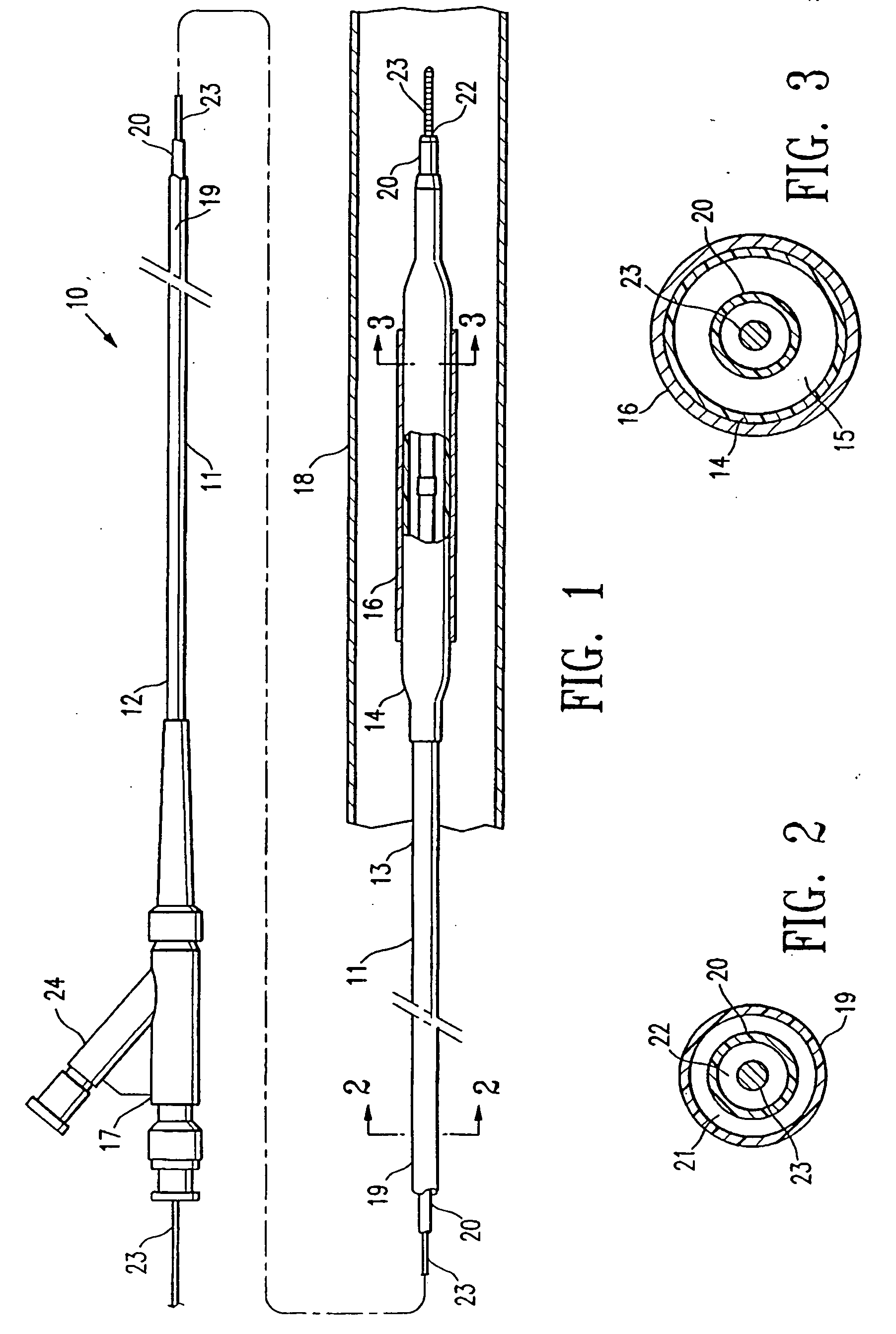
[0006] This invention is directed to a method of sterilizing a medical device component, such as a catheter balloon or shaft, in which an electron beam (i.e., e-beam) is applied to the component in an evacuated or
inert gas-filled container. The method of the invention allows for electron beam sterilization without significant degradation of the component polymeric material. It is believed that by minimizing the presence of air during the electron beam sterilization, the method inhibits or prevents the formation of reactive
oxygen and
nitrogen radicals which would otherwise form from the action of the
electron beam radiation on air. Another aspect of the invention is a medical device component, e-beam sterilized according to a method of the invention. A variety of medical device components can be sterilized by the method of the invention, and particularly intracorporeal devices for therapeutic or diagnostic purposes, such as balloon catheters, catheter shafts and balloons,
stent covers, and vascular grafts. In one embodiment, the device component is configured to be pressurized or expanded during use, and the method of the invention provides such a device component with a rupture pressure that is not significantly decreased due to electron beam sterilization. Although discussed primarily in terms of a balloon for a
balloon catheter, the invention should be understood to include other medical devices. The terminology “medical device component” should be understood to include an independent, complete item such as a
vascular graft or
balloon catheter, or alternatively, a part of a larger device such as a balloon or a shaft of a
balloon catheter.
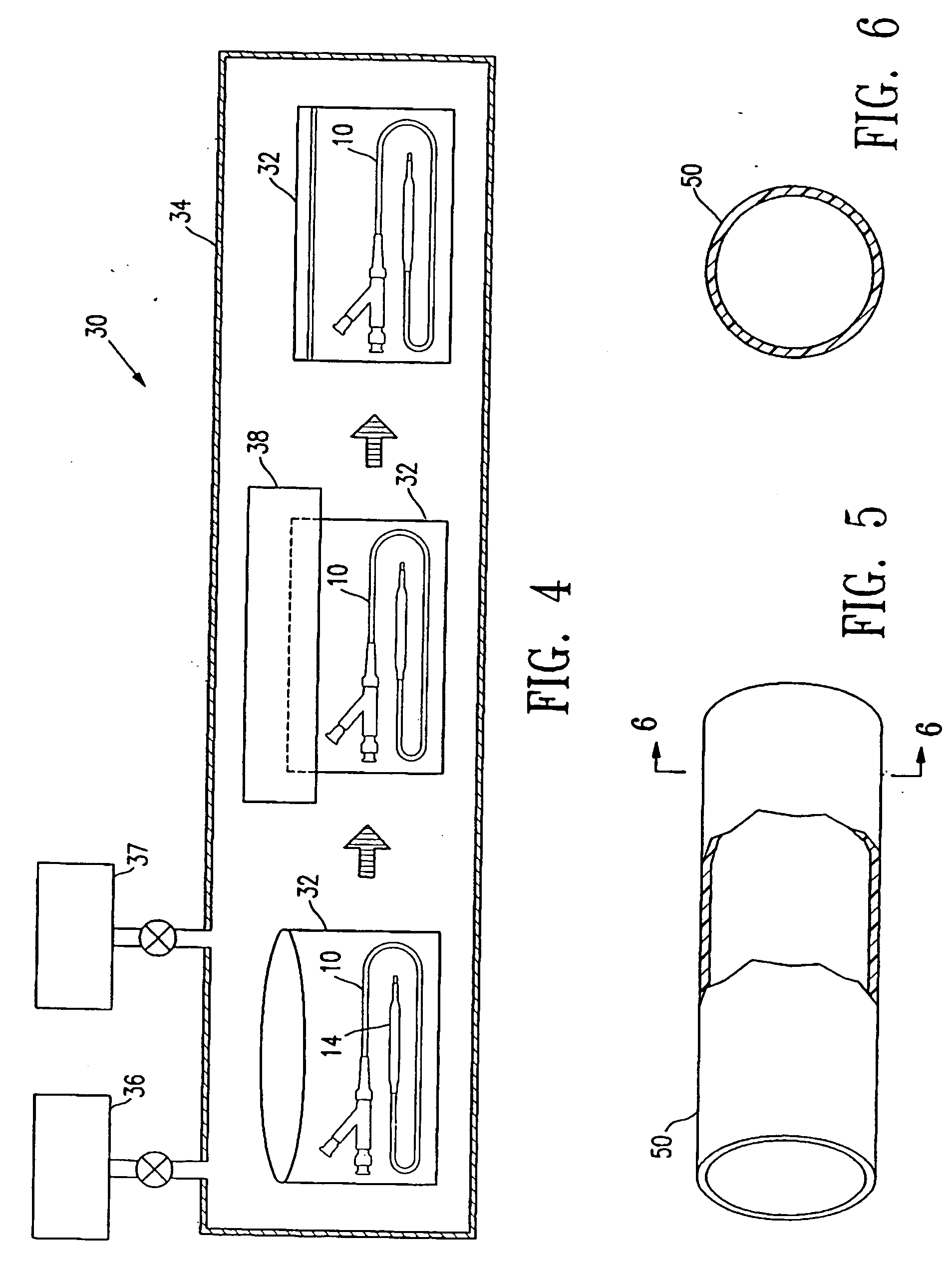
[0007] In one embodiment, the balloon itself, which has typically already been secured to a catheter shaft to form an assembled balloon catheter, is evacuated and / or filled with an
inert gas before the electron beam sterilization. In a presently preferred embodiment, the balloon is purged by applying a vacuum to evacuate the balloon and back filling the evacuated balloon with an
inert gas. Thus, the air which would have been present inside the balloon and catheter shaft interior is removed and replaced with an
inert gas before the electron beam sterilization. As a result, the degradation of the balloon polymeric material due to the electron beam sterilization is minimized. In a presently preferred embodiment, the balloon catheter is purged before being placed inside the container, and before the container is similarly purged by evacuating the container and back filling the container with an
inert gas. However, in an alternative embodiment, the balloon catheter is purged after being placed in the container.
[0009] In a presently preferred embodiment, the container is filled with inert gas so that the container has a
positive pressure which thus prevents or inhibits air leaking into the container in the event that pinholes develop in the container. The inert gas consequently prevents degradation of the balloon
polymer during or shortly after the electron beam application and the attendant loss of sterilization if pin holes develop in the container during storage of the catheter. However, in an alternative embodiment, the container is merely evacuated by applying a vacuum to the container and sealing the container, without necessarily filling the container with an inert gas before and the container sealed with the medical device component therein. The container and balloon are evacuated by applying a vacuum to an interior thereof to thereby reduce the
internal pressure therein to less than the
ambient pressure. For example, the absolute pressure in the
evacuated container is typically not greater than about 50 mTorr. After filling with the inert gas, the pressure inside the inert gas-filled container is typically not less than about 1 atm (760
Torr). In a presently preferred embodiment, the container (with the balloon catheter therein) is purged inside a
vacuum chamber. Thereafter, the container may be sealed inside the evacuated or inert gas-filled
vacuum chamber if the
vacuum chamber contains a sealer, or transferred to another vacuum chamber containing a sealer. Alternatively, the purged container may be removed from the vacuum chamber and maintained in an open end-up orientation and sealed outside the vacuum chamber.
Inert gas such as
argon is heavier than air and will thus prevent air going into the
argon-filled container when the container is held with the open end of the container up in an air-filled environment prior to sealing the container.
[0010] A catheter polymeric balloon sterilized according to the method of the invention has minimal degradation of the
polymer, and consequently, a minimal decrease in rupture pressure due to the sterilization. After the electron beam sterilization according to the method of the invention, the balloon has a mean rupture pressure which is not significantly less than (i.e., not more than 5% to about 25% less than, and preferably not more than about 10% to about 15% less than) the rupture pressure of the balloon before the electron beam sterilization of the method of the invention. Furthermore, the balloon preferably has a high
fatigue resistance, i.e., cycles to failure, which is not significantly less than (i.e., not more than about 5% to about 10% less than) the
fatigue resistance of the balloon before the electron beam sterilization of the method of the invention. After
accelerated aging to simulate
shelf life of the balloon in which the balloon is aged at about 45° C. to about 65° C. for about 1 to about 3 weeks, a balloon sterilized according to the method of the invention in an evacuated or inert gas-filled container has a mean rupture pressure which is significantly higher than (i.e., more than about 15% to about 25% higher than) the rupture pressure of a balloon electron beam sterilized in the presence of air although otherwise similarly aged and sterilized, and a
fatigue resistance which is significantly higher than (i.e., more than about 1000% to about 1500% higher than) the fatigue resistance of the balloon electron beam sterilized in the presence of air.
[0013] The sterilization method of the invention avoids significant degradation of the polymeric material of the medical device component, as a result of sterilizing the medical device component in an evacuated or inert gas-filled container. Consequently, the method provides a sterilized medical device component such as a catheter balloon having a sufficiently high rupture pressure, without requiring an increase in the wall thickness of the balloon. The method thus provides for improved manufacturability of the balloon catheter, and a balloon catheter having excellent performance characteristics such as low profile and flexibility, for excellent trackability, and a desired rupture pressure and fatigue resistance. These and other advantages of the invention will become more apparent from the following detailed description and accompanying exemplary drawings.

