Apparatus, method and article for direct slicing of step based nurbs models for solid freeform fabrication

a technology of step-based nurbs models and freeform fabrication, applied in the field of rapid prototyping, can solve the problems of large stl file sizes, and significant affecting the accuracy and quality of final parts produced by cad objects, so as to reduce or eliminate the problem associated, reduce the pre-processing time, and improve the model accuracy

Inactive Publication Date: 2006-07-13
THERICS
View PDF3 Cites 74 Cited by
  • Summary
  • Abstract
  • Description
  • Claims
  • Application Information

AI Technical Summary

Benefits of technology

[0013] Direct slicing of CAD models without the intermediate STL format seems to be a promising approach reducing or eliminating the problems associated with the currently available STL format. Direct slicing of the solid model keeps the geometric and topological robustness from the original data. Its advantages may include greater model accuracy, pre-processing time reduction, elimination of checking and repairing routines, and file size reduction as noted in the literature such as Jamieson, R., Hacker, H. “Direct slicing of CAD models for rapid prototyping,”Rapid Prototyping Journal, Vol. 1(2), 1995. Since the direct mathematical form...

Problems solved by technology

But with the rapid growth of the RP industry, particularly RP directed towards rapid manufacturing, rapid tooling and biomedical applications, there has been a growing dissatisfaction with this format among the RP community due to the limitations inherent within the format.
The geometric description used to represent solid CAD objects significantly affects the accuracy and quality of the final parts produced with this technology especially in the case of freeform shapes.
Tessellation involves approximation of surfaces with triangular facets which is undesirable in general, particularly when dealing with models that contain freeform shapes....

Method used


Image

  • Apparatus, method and article for direct slicing of step based nurbs models for solid freeform fabrication
  • Apparatus, method and article for direct slicing of step based nurbs models for solid freeform fabrication
  • Apparatus, method and article for direct slicing of step based nurbs models for solid freeform fabrication

Examples


case study examples

Implementation and Case Study Examples

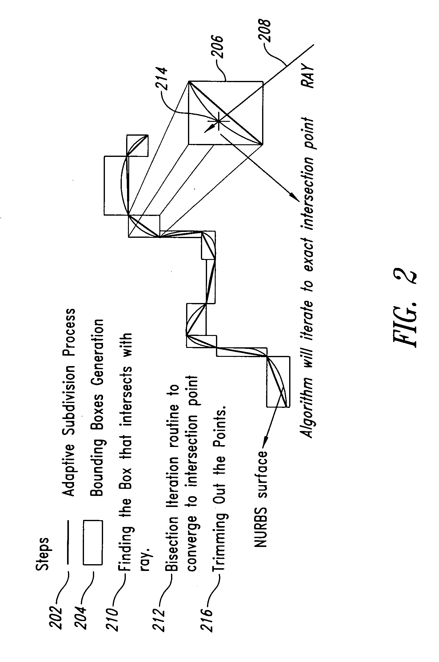
[0122] The algorithms may for example, be implemented in C++. Application of these algorithms to a variety of model shapes including simple NURBS surfaces, as well as complex curved NURBS surfaces provide three test cases, described below. FIG. 3 gives the generalized algorithm for ray-casting of NURBS surfaces that includes all of the steps outlined above.

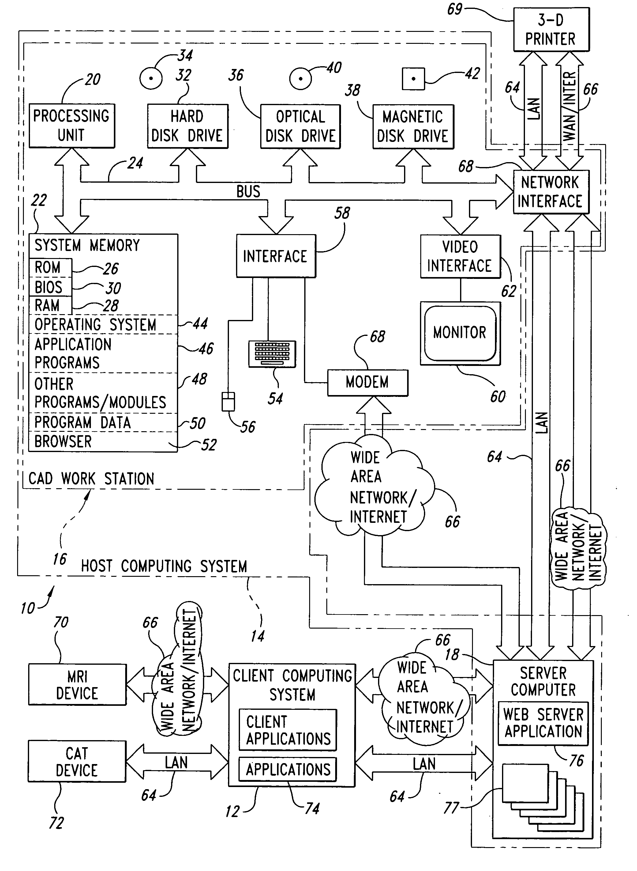
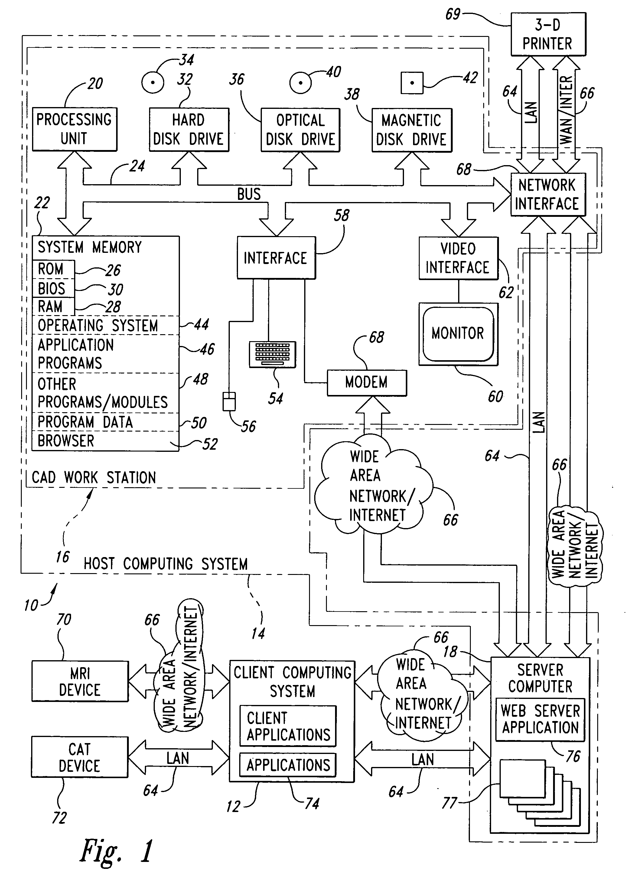
[0123]FIG. 6 details the data process planning algorithm 600 from the CAD file input stage to that of the final fabrication stage. For heterogeneous models, intersections of a ray to each geometric body are calculated in sequence. Thus the material associated with the geometric body being sliced can be captured and stored in the slicing data structure.

[0124] In step 602, the CAD workstation 16 receives a CAD file, for example, in STEP format. In step 604, the CAD workstation 16 operates on the CAD file using B-rep view tools. The CAD workstation 16 slices the resulting data using a slicing m...


PUM


Abstract

Direct slicing of CAD models to generate process planning instructions for solid freeform fabrication may overcome inherent disadvantages of using STL format in terms of the process accuracy, ease of file management, and incorporation of multiple materials. This paper will present the results of our development of a direct slicing algorithm for layered freeform fabrication. The direct slicing algorithm was based on a neutral, international standard (ISO 10303) STEP-formatted NURBS geometric representation and is intended to be independent of any commercial CAD software. The following aspects of the development effort will be presented: 1) Determination of optimal build direction based upon STEP-based NURBS models; 2) Adaptive subdivision of NURBS data for geometric refinement; and 3) Ray-casting slice generation into sets of raster patterns. Feasibility studies applying the direct slicing algorithm to example models and the generation of fabrication planning instructions involving multi-material structures will also be presented.

Description

BACKGROUND OF THE INVENTION [0001] 1. Field of the Invention [0002] This disclosure generally relates to the field of rapid prototyping and particularly to Layered Manufacturing (LM) or Solid Freeform Fabrication (SFF). [0003] 2. Description of the Related Art [0004] Layered Manufacturing or Solid Freeform Fabrication, a new class of manufacturing techniques introduced during the mid 1980s has grown rapidly over the past decade because of its proven ability to reduce product development cycle time. [0005] In the current industrial Rapid Prototyping (RP) practice, three-dimensional (3D) CAD data are first converted to an intermediate StereoLithography (STL) format, a tessellation procedure where the model is approximated by triangles, sliced and then fabricated by the machine. But with the rapid growth of the RP industry, particularly RP directed towards rapid manufacturing, rapid tooling and biomedical applications, there has been a growing dissatisfaction with this format among the...

Claims


Application Information

Patent Timeline
IPC IPC(8): G06F19/00
CPCG05B19/4099G05B2219/35133G05B2219/49013G05B2219/49014G06T17/30Y02P90/02
Inventor BRADBURY, THOMAS J.STARLY, BINILLAU, WING K.SUN, WEILAU, ALAN C.YOUSSEF, ADOLPHE H.GAYLO, CHRISTOPHER M.
Owner THERICS
Why Eureka
Try Eureka