Multi-well plate with alignment grooves for encoded microparticles

a microparticle and alignment groove technology, applied in the field of multi-well plate with alignment grooves for encoded microparticles, can solve the problems of insufficient different codes, inability to withstand harsh temperature, chemical, nuclear and/or electromagnetic environments, and insufficient existing technologies such as bar codes, to achieve the effect of rapid readout, low contrast and wide groove width

Inactive Publication Date: 2006-07-20
ILLUMINA INC
View PDF4 Cites 39 Cited by
  • Summary
  • Abstract
  • Description
  • Claims
  • Application Information

AI Technical Summary

Benefits of technology

[0014] The invention provides a method for aligning the microbeads in the two rotational axes to a fixed orientation relative to an incident laser beam and a readout camera, otherwise known as the code camera. The invention further provides a method for rapidly aligning a large number of microbeads, between 1,000 and 1,000,000 microbeads or more, economically, and with the necessary tolerances. The method is flexible as it relates to the size of the microbeads and can be integrated into a fully automated system, which prepares the microbeads for rapid readout by an automated code-reading machine.
[0015] In one embodiment of the present invention, the positioning device includes a plate with a series of parallel grooves, which could have one of several different shapes, including square, rectangular, v-shaped, semi-circular, etc., as well as a flat bottom groove with tapered walls. The grooves are formed into an optically transparent medium such as borosilicate glass, fused silica, or plastic. The depth of the grooves will depend on the diameter of the microbead but generally they will be between 10 and 125 μm, but may be l

Problems solved by technology

Existing technologies, such as bar codes, electronic microchips/transponders, radio-frequency identification (RFID), and fluorescence and other optical techniques, are often inadequate.
For example, existing technologies may be too large for certain applications, may not provide eno

Method used


Image

  • Multi-well plate with alignment grooves for encoded microparticles
  • Multi-well plate with alignment grooves for encoded microparticles
  • Multi-well plate with alignment grooves for encoded microparticles

Examples


Embodiment Construction

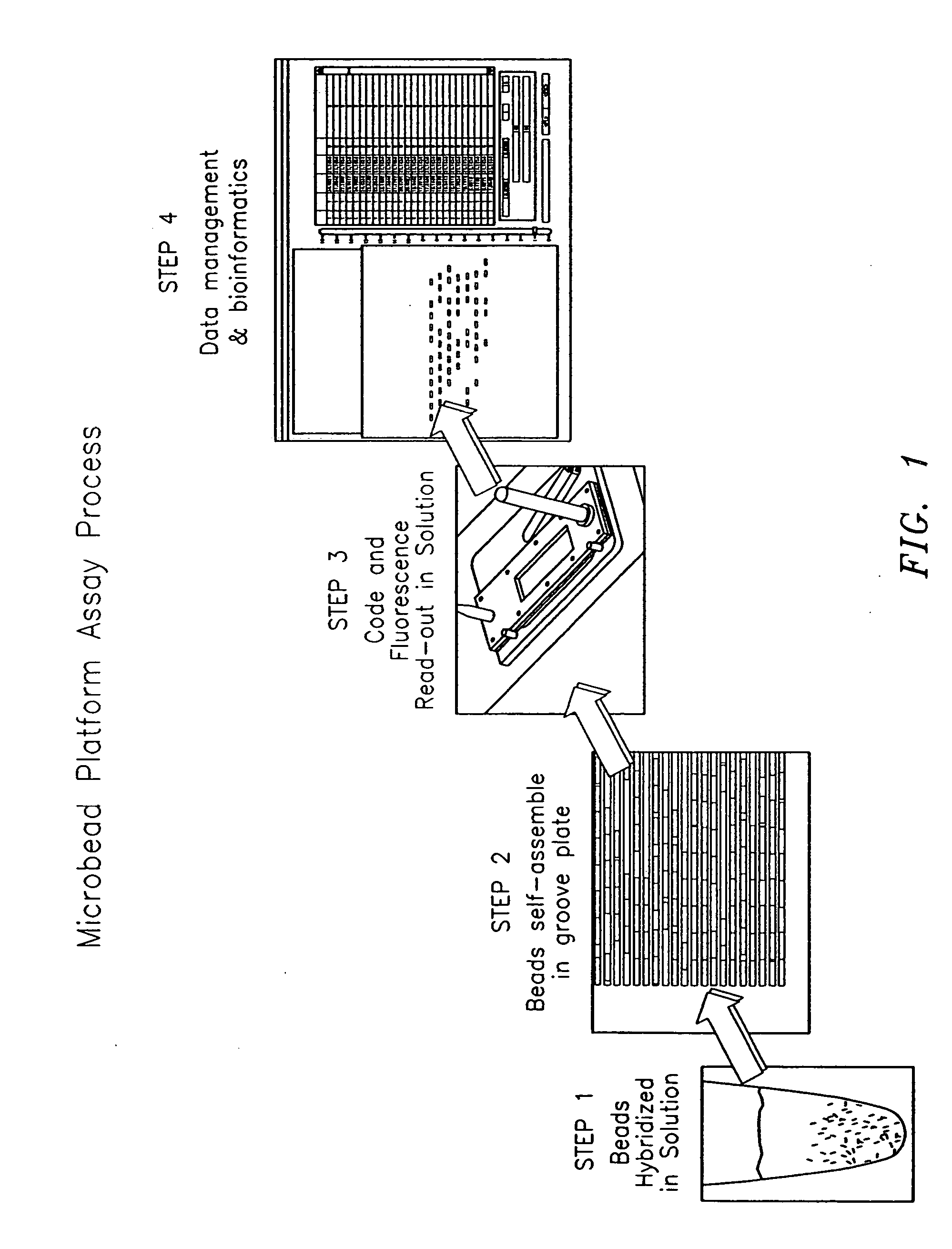
[0085]FIG. 1 shows, by way of example, steps of a microbead assay platform process which uses the microbead technology of the present invention. The steps of the assay process shown in FIG. 1 include a first step in which the microbeads are used or hybridized in a solution; a second step in which the microbeads are aligned or self-assembled in a desired manner; a third step in which the code and florescence in and / or on the microbeads are read-out in solution; and a fourth step in which the information related to the code and florescence is processed in relation to data management and bioinformatics. The present invention primarily relates to step 2 wherein the microbeads are uniquely aligned so the longitudinal axis of the microbeads is positioned in a fixed orientation relative to the code and florescence reading device, as well as relating to a lesser extent to step 3. It is important to note that the scope of the present invention is not intended to be limited to any particular ...


PUM


Abstract

A method and apparatus are provided for aligning optical elements or microbeads, wherein each microbead has an elongated body with a code embedded therein along a longitudinal axis thereof to be read by a code reading device. The microbeads are aligned with a positioning device so the longitudinal axis of the microbeads is positioned in a fixed orientation relative to the code reading device. The microbeads are typically cylindrically shaped glass beads between 25 and 250 microns (μm) in diameter and between 100 and 500 μm long, and have a holographic code embedded in the central region of the bead, which is used to identify it from the rest of the beads in a batch of beads with many different chemical probes. A cross reference is used to determine which probe is attached to which bead, thus allowing the researcher to correlate the chemical content on each bead with the measured fluorescence signal. Because the code consists of a diffraction grating typically disposed along an axis, there is a particular alignment required between the incident readout laser beam and the readout detector in two of the three rotational axes. The third axis, rotation about the center axis of the cylinder, is azimuthally symmetric and therefore does not require alignment.

Description

CROSS-REFERENCE TO RELATED APPLICATIONS [0001] This application is a continuation-in-part of, and relates and claims benefit to the following U.S. provisional patent application Ser. No. 60 / 546,435 (CV-0053PR), entitled “Multi-Well Plate With Alignment Grooves for Encoded Particles”, filed Feb. 19, 2004, which is hereby incorporated by reference in their entirety. [0002] This application also relates to U.S. provisional patent application Ser. Nos. 60 / 546,445 (CV-0035PR), entitled “Optical Identification Element Having Non-waveguide Photosensitive Substrate with Bragg Grating Therein”; and 60 / 547,013 (CV-0065PR), entitled “Optical Identification Element Using Separate or Partially Overlapping Diffraction Gratings”, all filed Feb. 19, 2004 and hereby incorporated by reference in their entirety, as well as their corresponding United States patent applications (CV-0035US and CV-0065US), as well as any corresponding PCT patent applications, all filed on this day contemporaneously with t...

Claims


Application Information

Patent Timeline
IPC IPC(8): C12M1/34G06K7/00G01N33/551C12M3/00
CPCG01N33/54313G01N33/54393
Inventor PUTNAM, MARTIN A.SIRKIS, JAMES S.MOON, JOHN A.LI, TUOTRAYNOR, JOSEPHBRUCATO, ROBERT N.
Owner ILLUMINA INC
Why Eureka
Try Eureka