Controlling flame temperature in a flame spray reaction process

a flame spray and reaction process technology, applied in the direction of metal/metal-oxide/metal-hydroxide catalysts, magnetic bodies, silicates, etc., can solve the problems of difficult control of the temperature of the flame therein, excessively high temperatures may be undesirable, and the size and other properties of nanoparticles may vary significantly, so as to reduce the temperature of the product particles

Inactive Publication Date: 2006-07-27
CABOT CORP
View PDF54 Cites 67 Cited by
  • Summary
  • Abstract
  • Description
  • Claims
  • Application Information

AI Technical Summary

Benefits of technology

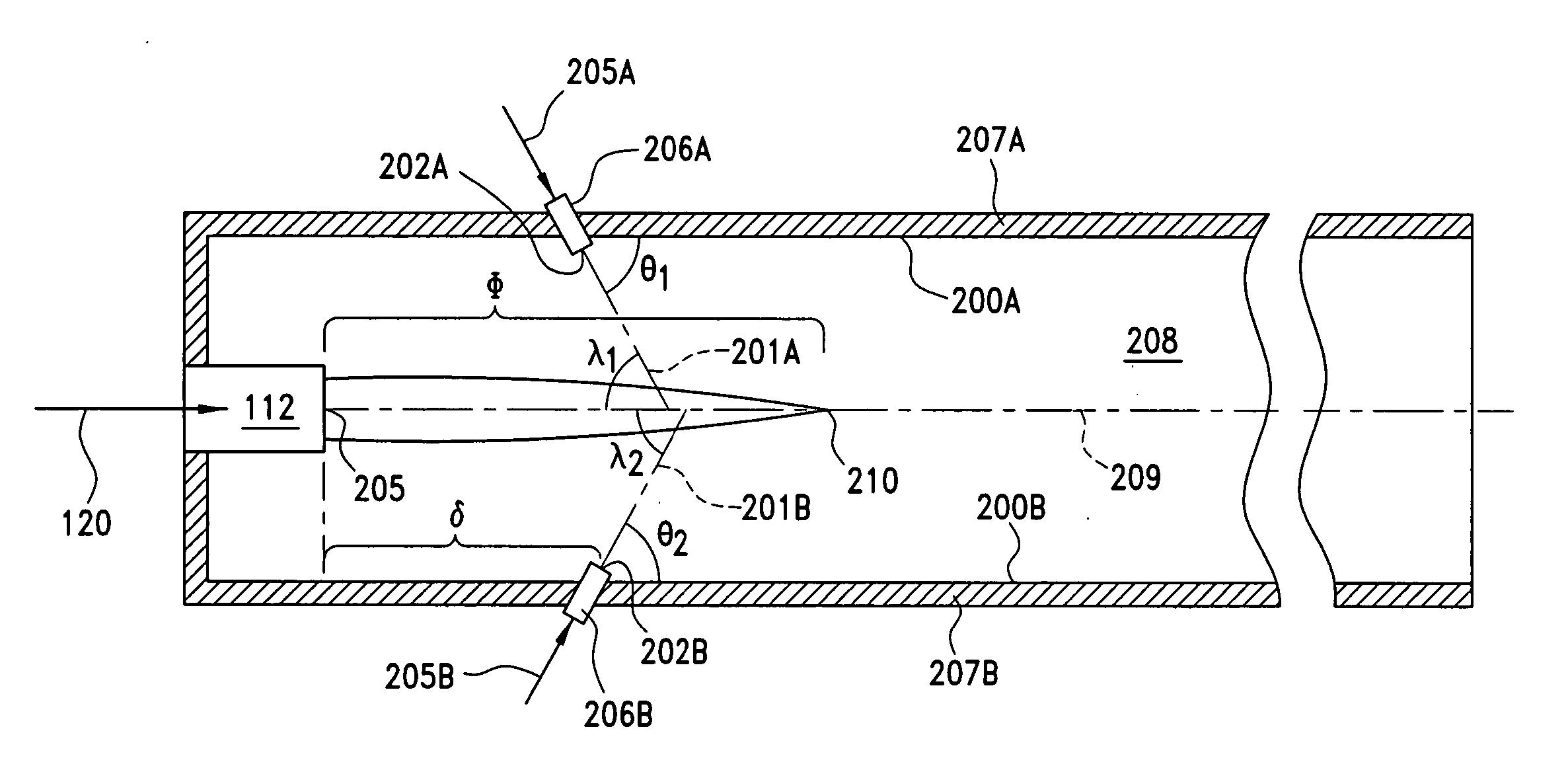
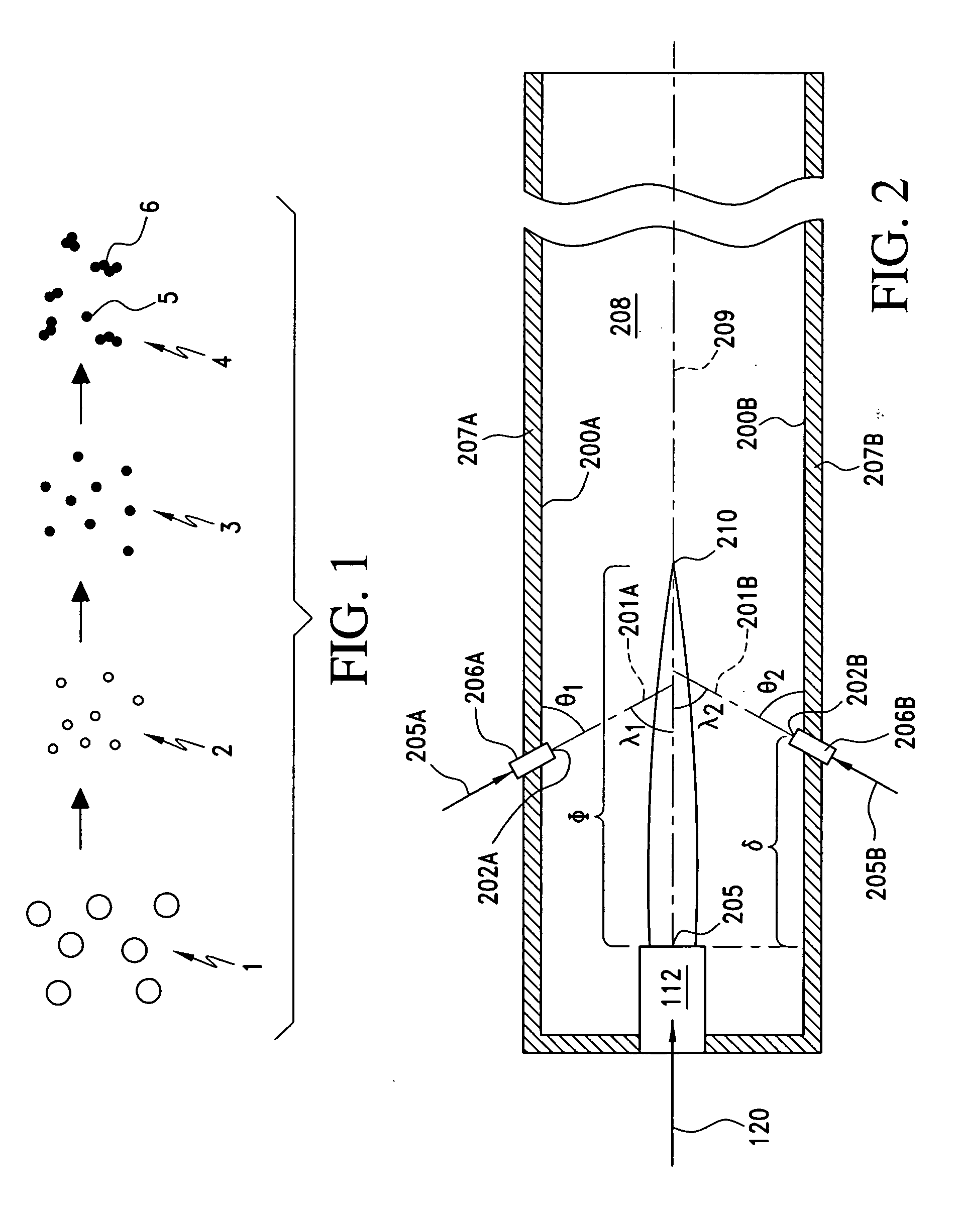
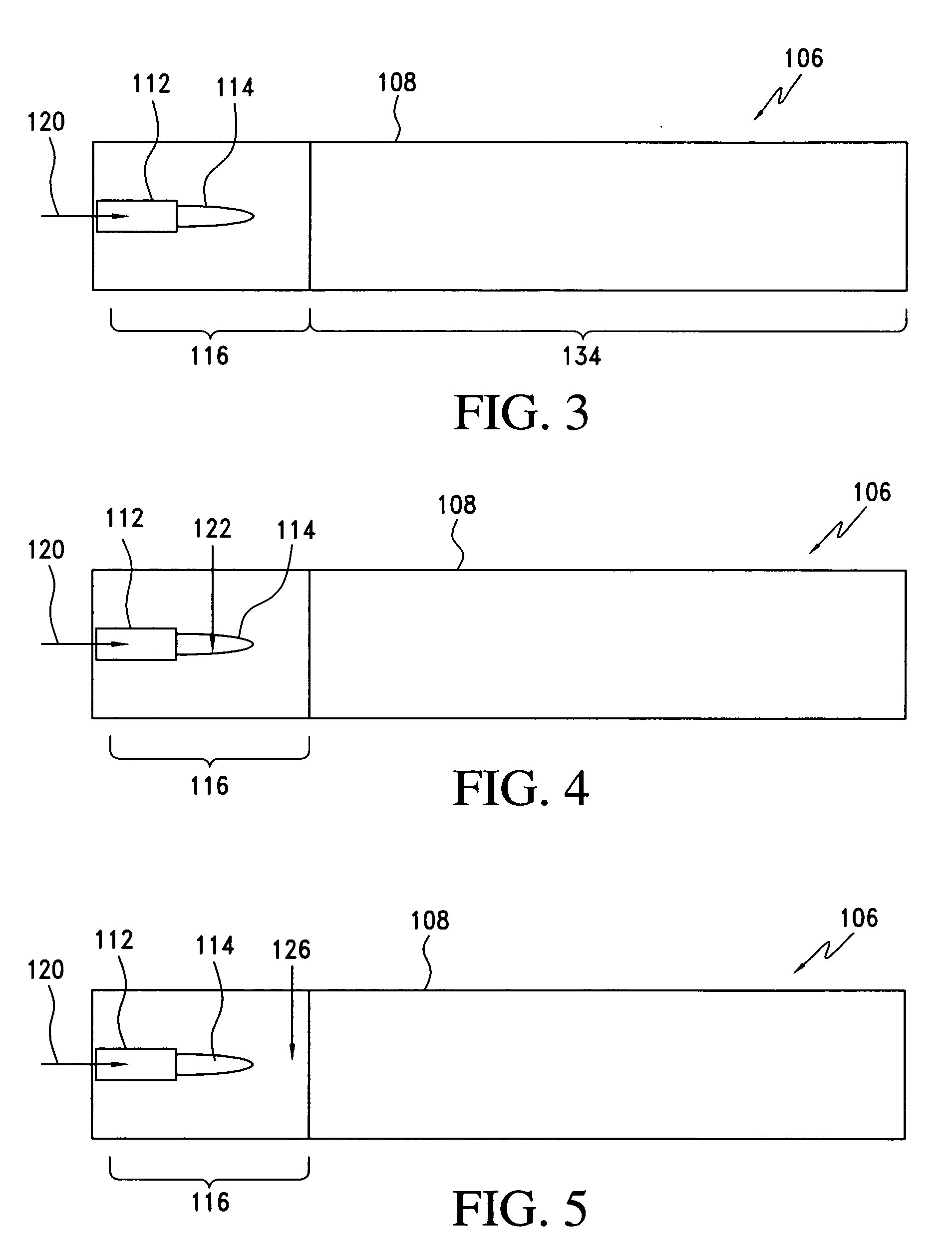
[0013] In still another aspect, the invention relates to a method of making product particles, the method comprising: introducing into a flame reactor heated by at least one flame, a precursor medium comprising a precursor to a component; forming the product particles, the forming comprising transferring substantially all of the precursor to a component through a gas phase of a flowing stream in the flame reactor and growing the product particles in the flowing stream to a weight average particle size in a range having a lower limit of 1 nanometer and an upper limit of 500 nanometers; and prior to completion of the growing, quenching the flowing stream in a first quenching step to reduce the temperature of the product particles, the quenching step comprising introducing into the flowing stream a cooling medium that is at a lower temperature than the flowing stream.
[0014] In yet another aspect, the invention relates to a method of making metal-containing product particles, the method comprising: introducing into a flame reactor heated by at least one flame a precursor medium comprising a precursor to a component; forming the product particles, the fo

Problems solved by technology

However, nanoparticles may range significantly in size and other properties.
One problem associated with conventional flame spray reaction systems is that it is difficult to control the temperature of the

Method used


Image

  • Controlling flame temperature in a flame spray reaction process
  • Controlling flame temperature in a flame spray reaction process
  • Controlling flame temperature in a flame spray reaction process

Examples


example 1

Cerium Oxide

[0221] Cerium 2-ethylhexanoate mixed with toluene is used as the precursor solution for the synthesis of ceria powder. The cerium metal weight percent in the precursor solution varied from 6 to 7.7. The precursor flow rate and dispersion oxygen flow rate were 15 ml / min and 25 SLPM, respectively. Different furnaces were used to change the residence time and temperature profile in the reactor. The surface area of particles varied from 48 m2 / gm to 179 m2 / gm. Scanning electron microscopy (SEM) and tunneling electron microscopy (TEM) analysis of the powder shows that primary particle size varied from 15 to 25 nm and the primary aggregate size varied from 50 to 100 nm. The synthesized ceria powders can be used for catalyst support, chemical mechanical polishing, and as an electrocatalyst.

example 2

Silicon Titanium Oxide Powder

[0222] Titanium Diisopropoxide and hexamethyldisiloxane mixed with ethanol is used as the precursor solution for the synthesis of silicon titanium oxide powder. The precursor flow rate varied from 15 to 40 ml / min and dispersing oxygen flow rate varied from 25 to 50 SLPM. The surface area of particles varied from 34 to 120 m2 / gm. The synthesized silicon titanium oxide powders can be used as catalyst and fillers.


PUM

PropertyMeasurementUnit
Temperatureaaaaaaaaaa
Angleaaaaaaaaaa

Abstract

The invention relates to a process for decreasing flame temperature in a flame spray reaction system, the process comprising the steps of providing a precursor medium comprising a precursor to a component; flame spraying the precursor medium under conditions effective to form a population of product particles; and decreasing the flame temperature by contacting the flame with a cooling medium. The process of the present invention allows for the control of the size, composition and morphology of the nanoparticles made using the process. The invention also relates to a nozzle assembly that comprises a substantially longitudinally extending atomizing feed nozzle that comprises an atomizing medium conduit and one or more substantially longitudinally extending precursor medium feed conduits. The nozzle assembly of the present invention is used in a flame spray system to produce nanoparticles using the processes described herein.

Description

CROSS REFERENCE TO RELATED APPLICATION [0001] This application claims the benefit of U.S. Provisional Application Ser. No. 60 / 645,985, filed Jan. 21, 2005, the entire contents of which are incorporated herein by reference.FIELD OF INVENTION [0002] The present invention relates to flame spray reaction processes, and more particularly, to controlling flame temperature in flame spray reaction processes. BACKGROUND OF THE INVENTION [0003] There is currently a heightened interest in the use of nanoparticles for a variety of applications. However, nanoparticles may range significantly in size and other properties. For example, particles ranging in size from 1 nm to 500 nm are still considered nanoparticles. For different applications, however, particle sizes or particle size distributions may vary based on product or processing requirements. Also, for some applications, certain characteristics for other properties may be desired, such as the density or morphology of the nanoparticles. [00...

Claims


Application Information

Patent Timeline
IPC IPC(8): H05H1/26B05D1/08B05C11/00B05C5/00B22F1/054
CPCB01J23/42H01F1/0054B01J35/006B01J37/086B01J37/349B22F1/0018B22F9/026B82Y25/00B82Y30/00C01B33/18C01B33/26C01G1/00C01G1/02C01G23/07C01G49/0018C01P2004/03C01P2004/04C01P2004/62C01P2004/64C01P2006/12C01P2006/13C23C4/121C23C4/124C23C18/02C23C18/1216C23C18/1258C23C18/1295F23D99/003F23D2900/21007H01M4/8621H01M4/8652H01M4/8832H01M4/8835H01M4/8885H01M4/9016H01M2008/1293Y02E60/50Y02E60/525B01J23/745F23D91/02C23C4/129C23C4/123B22F1/054B22F1/056
Inventor KODAS, TOIVO T.FOTOU, GEORGE P.OLJACA, MIODRAGHARDMAN, NED JAYKUMAR, PRAKASH
Owner CABOT CORP
Why Eureka
Try Eureka