Rigid-flex wiring board

a technology of rigid substrates and wiring boards, which is applied in the field of rigid rigid substrate wiring boards, can solve the problems of inability to produce any higher yield, scratching of rigid substrate surfaces, and relatively long time-consuming process, and achieves the effects of reducing inductance, high reliability, and high freedom of wiring

Inactive Publication Date: 2006-08-03
IBIDEN CO LTD
View PDF9 Cites 90 Cited by
  • Summary
  • Abstract
  • Description
  • Claims
  • Application Information

AI Technical Summary

Benefits of technology

[0018] The present invention has an object to overcome the above-mentioned drawbacks of the related art by providing a flex-rigid wiring board effective for reduction of the inductance in a high-frequency ...

Problems solved by technology

21(b) is complicated, the lead time for this process is relatively long.
It is also disadvantageous in that in the step of cutting off a part of the rigid substrates (as shown in FIG. 21(d)), positioning in the direction of thickness has to be done accurately and cutting off the parts of the rigid substrates with a cutting tool or the like is often likely to result in scratching of the surfaces of the rigid substrates.
Also, the conventional flex-rigid wiring board is not advantageous in that it cannot be produced with any higher yield since it is formed from a combination of different materials, which leads to a displacement of them from each other due to a difference in thermal shrinkage between them during the thermal compression bonding, smear developed at the time of drilling, poor adhesion of the through-hole plating or the like.
Further, the conventional flex-rigid wiring board is disadvantageous in that the inter-layer connection is not highly reliable since the through-hole plate is likely to break away at the boundary between the through-hole form...

Method used


Image

  • Rigid-flex wiring board
  • Rigid-flex wiring board
  • Rigid-flex wiring board

Examples


example 1

[0139] (A) Preparation of a Flexible Substrate

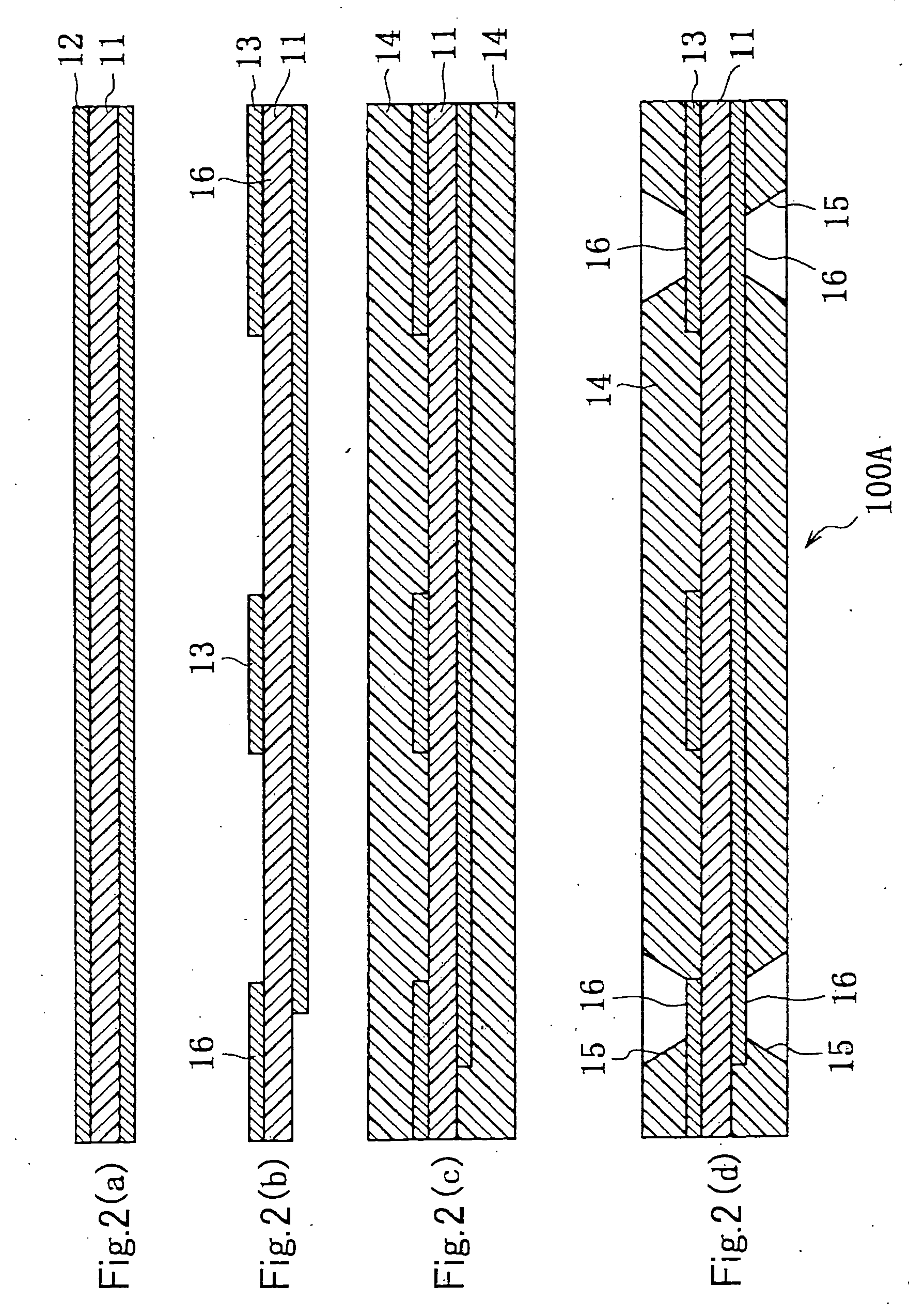
[0140] (1) For manufacturing the flex-rigid wiring board according to the present invention, a laminated film (ESPANEX SB by Shin-Nittetsu Chemicals) including a 25 μm-thick insulative film 11 of polyimide resin having an 18 μm-thick copper foil 12 laminated on either side thereof (as in FIG. 2(a)) was used as a base material for preparation of a flexible substrate 100A included in the flex-rigid wiring board.

[0141] (2) The copper foil 12 laminated on either side of the insulative film 11 was etched using a cupric chloride aqueous-solution to form patterns 13 and 250 μm-diameter interconnecting electrode pads 16. A photosensitive epoxy resin (FR-5538EA by Hitachi Chemical) was applied to the wiring pattern, dried at 80° C. for 3 hours, then exposed to ultraviolet rays, and developed using dimethyleneglycol diethylether to form a 25 μm-thick resin cover layer 14 which has 300 μm-diameter openings 15 formed therein and protects the patte...

example 2

[0153] (A) Preparation of a Flexible Substrate

[0154] (1) For manufacturing the flex-rigid wiring board according to the present invention, a laminated film (ESPANEX SB by Shin-Nittetsu Chemicals) including a 25 m-thick insulative film 11 of polyimide resin having an 18 μm-thick copper foil 12 laminated on either side thereof was used as a base material for preparation of a flexible substrate included in the flex-rigid wiring board.

[0155] (2) The copper foil 12 laminated on either side of the insulative film 11 was etched using a cupric chloride aqueous-solution to form patterns 13, and a cresol-novolak epoxy resin (by Nihon Kayaku) of 60% by weight solved in dimethylglycol dimethylether was applied to the patterns 13. The resin was dried at 80° C. for 3 hours to form an uncured epoxy resin layer 50 (adhesive layer). Thus, a flexible substrate 100B was prepared.

[0156] (B) Preparation of a Rigid Substrate

[0157] (1) In a 0.11 mm-thick single-sided copper-clad laminate (as in FIG. 6...

example 3

[0169] (A) Preparation of a Flexible Substrate

[0170] (1) For manufacturing the flex-rigid wiring board according to the present invention, a laminated film (ESPANEX SB by Shin-Nittetsu Chemicals) including a 25 μm-thick insulative film 11 of polyimide resin having an 18 μm-thick copper foil 12 laminated on either side thereof was used as a base material for preparation of a flexible substrate included in the flex-rigid wiring board.

[0171] (2) The copper foil 12 laminated on either side of the insulative film 11 was etched using a cupric chloride aqueous-solution to form patterns 13, and a novolak epoxy resin (by Nihon Kayaku) of 60% by weight solved in dimethylglycol dimethylether was applied to the patterns 13. The resin was dried at 80° C. for 3 hours to form an uncured epoxy resin layer 50. Thus, a flexible substrate was prepared.

[0172] (B) Preparation of a Rigid Substrate

[0173] (1) In a 0.11-mm single-sided copper-clad laminate (as in FIG. 6(a)) including a substrate 21 of g...


PUM


Abstract

A flex-rigid wiring board has an insulative adhesive interposed between portions, lapping over each other, of the rigid and flexible substrates; and the interconnecting electrode pads on the rigid and flexible substrates are electrically connected to each other through a conductor lump penetrating the insulative adhesive, thereby providing lowered inductance in the high-frequency band, shortened signal-delay time, reduced noise generation due to signal reflected-wave, reduced drop impact, high connection reliability and high freedom of wire connection, and the wiring board can advantageously be manufactured with a reduced cost and a high yield.

Description

FIELD OF THE INVENTION [0001] The present invention generally relates to a wiring board including a flexible substrate and rigid substrate, and more particularly to a flex-rigid wiring board wherein a flexible substrate and rigid substrate are lap-joined to each other in a rigid portion of the wiring board. BACKGROUND ART [0002] The recent portable electronic devices such as a foldable mobile phone and the like use a flex-rigid multilayer wiring board. FIG. 20 shows an example of such a conventional wiring board, in which rigid portions 500 and 520 are connected to a flexible portion 510 through a flexible substrate 544. Normally in the rigid portion 500, the flexible substrate 544 and pattern layers 504 and 506 on the surfaces of the rigid portions 500 and 520 are electrically connected to each other through a conductive layer in a plated through-hole 502 (cf. Japanese Patent Application Laid Open No. 90756 of 1993). [0003] The conventional flex-rigid multilayer wiring board is man...

Claims


Application Information

Patent Timeline
IPC IPC(8): H05K1/00H05K3/00H05K3/46
CPCH05K3/4614H05K3/462H05K3/4691H05K2203/1189H05K3/46H05K3/40H05K1/11
Inventor KAWAGUCHI, KATSUOFUTAMURA, HIROFUMI
Owner IBIDEN CO LTD
Why Eureka
Try Eureka