Method and apparatus for stimulus artifact suppression

a stimulus and artifact technology, applied in the field of evoked potential and nerve conduction testing, can solve the problems of amplifiers recovering from saturation condition, amplifier gains are typically set very high, and significant difficulty in measuring response potentials, so as to reduce the overall gain of the amplifying apparatus and achieve high gain amplification, the effect of high gain

Active Publication Date: 2006-08-03
NATUS MEDICAL
View PDF8 Cites 5 Cited by
  • Summary
  • Abstract
  • Description
  • Claims
  • Application Information

AI Technical Summary

Benefits of technology

[0007] The evoked potential amplifying apparatus of the invention receives the evoked potential signal from the sensing electrodes and a stimulus signal from a stimulator that indicates when a stimulus pulse is applied. The amplifying apparatus includes a first or feed-forward amplifying section having an input receiving a signal from the evoked potential electrodes and providing an amplified output signal, and a second amplifier section receiving the output of the first or feed-forward amplifying section and providing an output signal, the first and second amplifying sections connected in a feedback circuit to provide high gain amplification of the evoked potential signal. A coupling capacitor is connected in a feedback loop to the input of the second amplifier section to configure the second amplifier section as an integrator. This configuration allows the evoked potential signal to pass through while blocking DC components. A controllable switch is connected across the first amplifier section from its inverting input to its output. The controllable switch receives a switch control signal indicating the application of a stimulus pulse to close the controllable switch and ‘short out’ the fir

Problems solved by technology

A significant difficulty is encountered in measuring the response potentials because the electrical stimulator produces a large electric field potential.
This field potential reaches the recording electrodes almost instantly and generates a response commonly referred to as the “stimulus artifact.” This artifact is problematic for two reasons.
First, since the response potential is so small, the amplifier gains are typically set very high.
As a result

Method used


Image

  • Method and apparatus for stimulus artifact suppression
  • Method and apparatus for stimulus artifact suppression
  • Method and apparatus for stimulus artifact suppression

Examples


Embodiment Construction

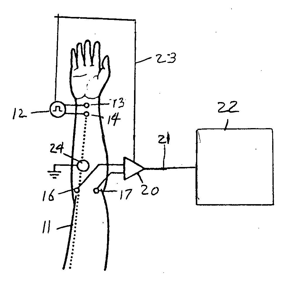
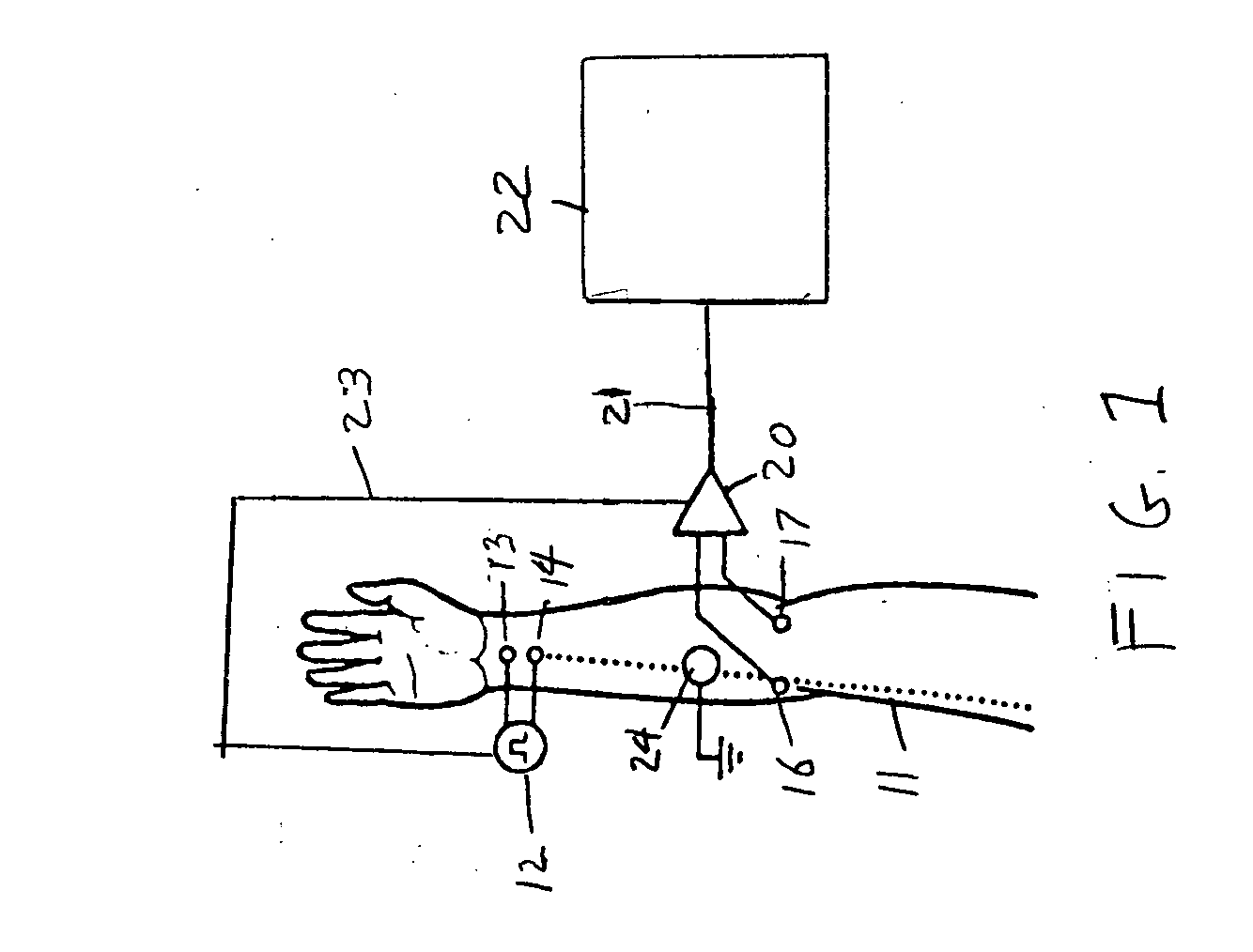
[0014] A pictorial view illustrating a typical application of evoked potential stimulation apparatus is shown in FIG. 1 to provide an example of the invention, arranged for measuring the response of the median nerve in a subject's arm 11. The electrical stimulus is provided from a stimulator 12 to anode and cathode stimulation electrodes 13 and 14, respectively. An example of stimulation apparatus for applying electrical stimulus pulses to a subject is described in U.S. Pat. No. 4,722,343, issued Feb. 2, 1988, the disclosure of which is incorporated herein by reference. The nerve response signal is recorded at sensing electrodes 16 and 17 which are connected to and the signals from which are received by a recording amplifier 20 in accordance with the invention, which provides its amplified output signal on a line 21 to an analyzer 22. The stimulus pulse from the stimulator 12 is supplied via a connecting line 23 to the recording amplifier 20 for use in accordance with the invention,...


PUM


Abstract

Amplification of an evoked potential signal is carried out utilizing a high pass filter implemented as an integrator in a feedback loop which drives the DC offset voltage to zero. As a result, the feed-forward amplifier circuit has almost zero volts at its output since the only voltage remaining is the offset voltage of the operational amplifier, which is selected so as to maintain this parameter as low as possible. Because the voltage impressed across the feed-forward amplifier section is close to zero, the gain of this section can be set to zero during the time that the electrical stimulus pulse is present without introducing any additional artifacts and subsequent amplifier stages are not driven into saturation. When the electrical stimulus potential is no longer present or is significantly reduced in amplitude and before the time of receipt of the response signal, the feed-forward amplifier is brought back into the circuit to provide the high gain required to amplify the response signal, which can be measured without interference from saturation of any of the amplifier stages as they recover to baseline.

Description

FIELD OF THE INVENTION [0001] This invention relates generally to the field of evoked potential and nerve conduction testing and to instruments which apply electrical pulses to an individual to stimulate nerves and generate evoked potentials. BACKGROUND OF THE INVENTION [0002] Nerve conduction studies and evoked potential measurements are now commonly made in clinical practice and in research to evaluate nervous system functions. To measure the evoked potentials stimulated by electrical pulses, surface measurement electrodes are customarily positioned on the scalp or skin over peripheral nerves. The electrical potentials received by these electrodes are detected and analyzed by sensitive recording equipment. To stimulate a response in the nervous system, stimulation electrodes are applied to the skin of the subject at a position remote from the measurement electrodes, typically on an arm or leg, and a pulse of either constant voltage or constant current magnitude is then applied to ...

Claims


Application Information

Patent Timeline
IPC IPC(8): A61N1/00
CPCA61B5/04001A61N1/36014A61B5/7217A61B5/24
Inventor LOMBARDI, DANIEL J.VOS, STEVEN
Owner NATUS MEDICAL
Why Eureka
Try Eureka