Gas turbine blade having a monocrystalline airfoil with a repair squealer tip, and repair method

Active Publication Date: 2006-08-10
GENERAL ELECTRIC CO
View PDF3 Cites 19 Cited by
  • Summary
  • Abstract
  • Description
  • Claims
  • Application Information

AI Technical Summary

Benefits of technology

[0012] The reduction in and resulting low content of the grain-boundary strengthening elements carbon, boron, silicon, zirconium, and hafnium in the second nickel-base superalloy has little adverse effect on the properties of the repair squealer tip, because the grain-boundary strengthening imparted by these elements is not required. The squealer tip is not strength limited due to its location at the end of the turbine blade. Consequently, omission of the grain-boundary strengthening elements from the second nickel-base sup

Problems solved by technology

After a period of time in service, the tip of the turbine blade (called a “squealer tip”) is typically eroded, oxidized, and corroded by the impingement of the hot combustion gases.
In most cases the repair squealer tip material cannot be the same nickel-base superalloy as the airfoil beca

Method used


Image

  • Gas turbine blade having a monocrystalline airfoil with a repair squealer tip, and repair method
  • Gas turbine blade having a monocrystalline airfoil with a repair squealer tip, and repair method
  • Gas turbine blade having a monocrystalline airfoil with a repair squealer tip, and repair method

Examples


Embodiment Construction

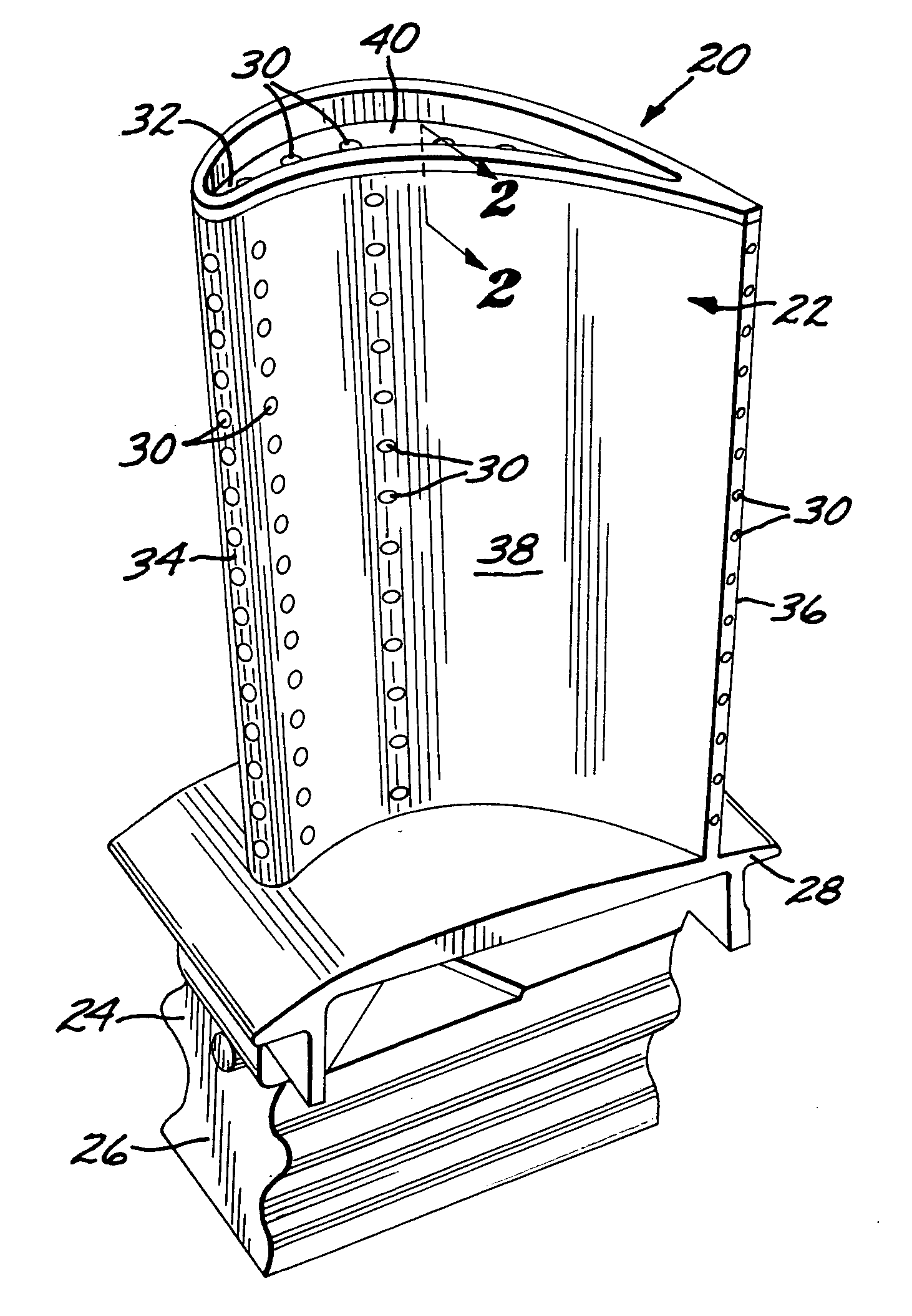
[0018]FIG. 1 depicts a gas turbine blade 20 which has preferably previously been in service. The previous service is operation in a gas turbine engine in its normal operating circumstances. The gas turbine blade 20 has an airfoil 22 against which the flow of hot combustion gas impinges during service operation, a downwardly extending shank 24, and an attachment in the form of a dovetail 26 which attaches the gas turbine blade 20 to a gas turbine disk (not shown) of the gas turbine engine. A platform 28 extends transversely outwardly at a location between the airfoil 22, and the shank 24 and dovetail 26. The airfoil 22 may be hollow so that cooling air may be forced through the airfoil 22, with the flow of cooling air exiting the airfoil 22 through air-flow holes 30 found on a tip 32, a leading edge 34, a trailing edge 36, and the lateral sides 38 of the airfoil 22.

[0019] In advanced gas turbine engines, the airfoil 22 (and desirably the remainder of the gas turbine blade 22) is mon...


PUM

PropertyMeasurementUnit
Fractionaaaaaaaaaa
Fractionaaaaaaaaaa
Fractionaaaaaaaaaa

Abstract

A repaired gas turbine blade includes a turbine blade body having a monocrystalline airfoil made of a first nickel-base superalloy, and a repair squealer tip welded to a tip of the airfoil. The repair squealer tip is made of a second nickel-base superalloy different from the first nickel-base superalloy and having less than about 0.15 weight percent total of carbon, boron, silicon, zirconium, and hafnium.

Description

[0001] This invention relates to the repair of the tip of the airfoil of a gas turbine blade and, more particularly, to selection of a nickel-base superalloy for the repair squealer tip. BACKGROUND OF THE INVENTION [0002] In an aircraft gas turbine (jet) engine, air is drawn into the front of the engine, compressed by a shaft-mounted compressor, and mixed with fuel. The mixture is burned, and the hot combustion gases are passed through a turbine mounted on the same shaft. The flow of combustion gas turns the turbine by impingement against an airfoil section of the turbine blades and vanes, which turns the shaft and provides power to the compressor and fan. In a more complex version of the gas turbine engine, the compressor and a high pressure turbine are mounted on one shaft, and the fan and low pressure turbine are mounted on a separate shaft. The hot exhaust gases flow from the back of the engine, driving it and the aircraft forward. [0003] After a period of time in service, the t...

Claims


Application Information

Patent Timeline
IPC IPC(8): B23P6/00F03B3/12B32B15/01
CPCB23P6/007F01D5/005F01D5/20Y02T50/673F05D2230/80Y10T29/49336Y10T29/49737Y10T428/12944Y10T29/49318Y10T29/49732Y10T29/49734Y10T29/49337Y02T50/60
Inventor ROEDL, LAWRENCE JOSEPHHENSLEY, RABON
Owner GENERAL ELECTRIC CO
Why Eureka
Try Eureka