Sealing arrangement for use in evacuating a glass chamber

a technology for sealing arrangements and glass chambers, applied in mechanical equipment, packaging, transportation and packaging, etc., can solve the problems of not being able to meet the requirements of requiring a more complex and expensive vacuum system, and the temperature of glass sheets during the evacuation process is limited to about 220° c, so as to reduce the variation in thickness and reduce the variation in point-to-point thickness. , the effect of reducing the quality of the vacuum seal

Inactive Publication Date: 2006-08-10
THE UNIV OF SYDNEY
View PDF14 Cites 29 Cited by
  • Summary
  • Abstract
  • Description
  • Claims
  • Application Information

AI Technical Summary

Benefits of technology

[0023] In the arrangement where the gasket is profiled to include raised regions and at least one groove, the material from the raised regions may not completely fill the grooved regions. If a spiral groove is used, narrow leakage paths therefore exist on both sides of the gasket, across the sealing surfaces of the evacuation head, through these incompletely filled spiral grooves. A simple calculation shows that a negligible quantity of air leaks along these grooves during production of a glass panel. The existence of this spiral leakage channel therefore does not significantly degrade the quality of the vacuum seals.
[0024] In one form, the gasket is pressed to limit the variation in thickness and / or to profile the gasket surface(s). In another form, photolithographic techniques could also be used to produce the grooved structure directly onto the surface of the gasket. If this method were to be used, preferably, the gasket material itself is sufficiently uniform in thickness that the deformation caused during its use with the evacuation head is sufficient to achieve a vacuum seal of adequate quality. The point-to-point variations in thickness of conventionally rolled aluminium foil are much larger than desirable when it is used as a gasket to seal the evacuation head to a glass sheet. It is possible that specialized rolling techniques may reduce the point-to-point variations in thickness compared with conventionally rolled aluminium foil, and that foil produced in this way would be suitable if the grooves were to be produced photolithographically.

Problems solved by technology

In this case, the temperature of the glass sheets during the evacuation process is limited to about 220° C., because the o-ring materials decompose at higher temperatures.
This is not possible if an o-ring is used to seal the evacuation cup to the glass sheet, however because the material of the o-ring will not survive the high temperature of the edge seal process.
Whilst such multiple pumping techniques work very satisfactorily, they do require a more complex and expensive vacuum system.
Another problem of the evacuating head is that the direct contact between the metal sealing surfaces of the cup and the surface of the glass sheet can produce marks on the glass surface.
Although these marks do not significantly weaken the glass, they are undesirable because they are cosmetically unattractive in the completed evacuated panel.
However, previously, the use of the gasket has not allowed a level of vacuum to be achieved that is required in highly insulating designs of vacuum glazing and for plasma display panels.

Method used


Image

  • Sealing arrangement for use in evacuating a glass chamber
  • Sealing arrangement for use in evacuating a glass chamber
  • Sealing arrangement for use in evacuating a glass chamber

Examples


Embodiment Construction

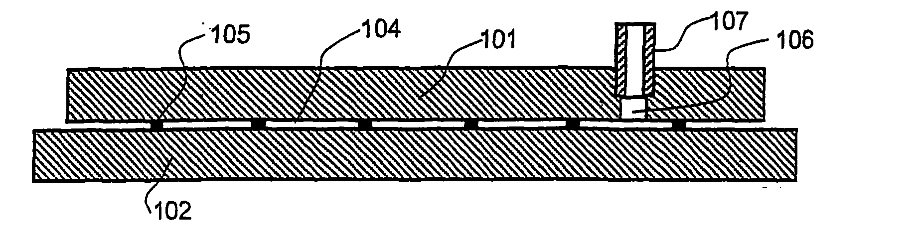
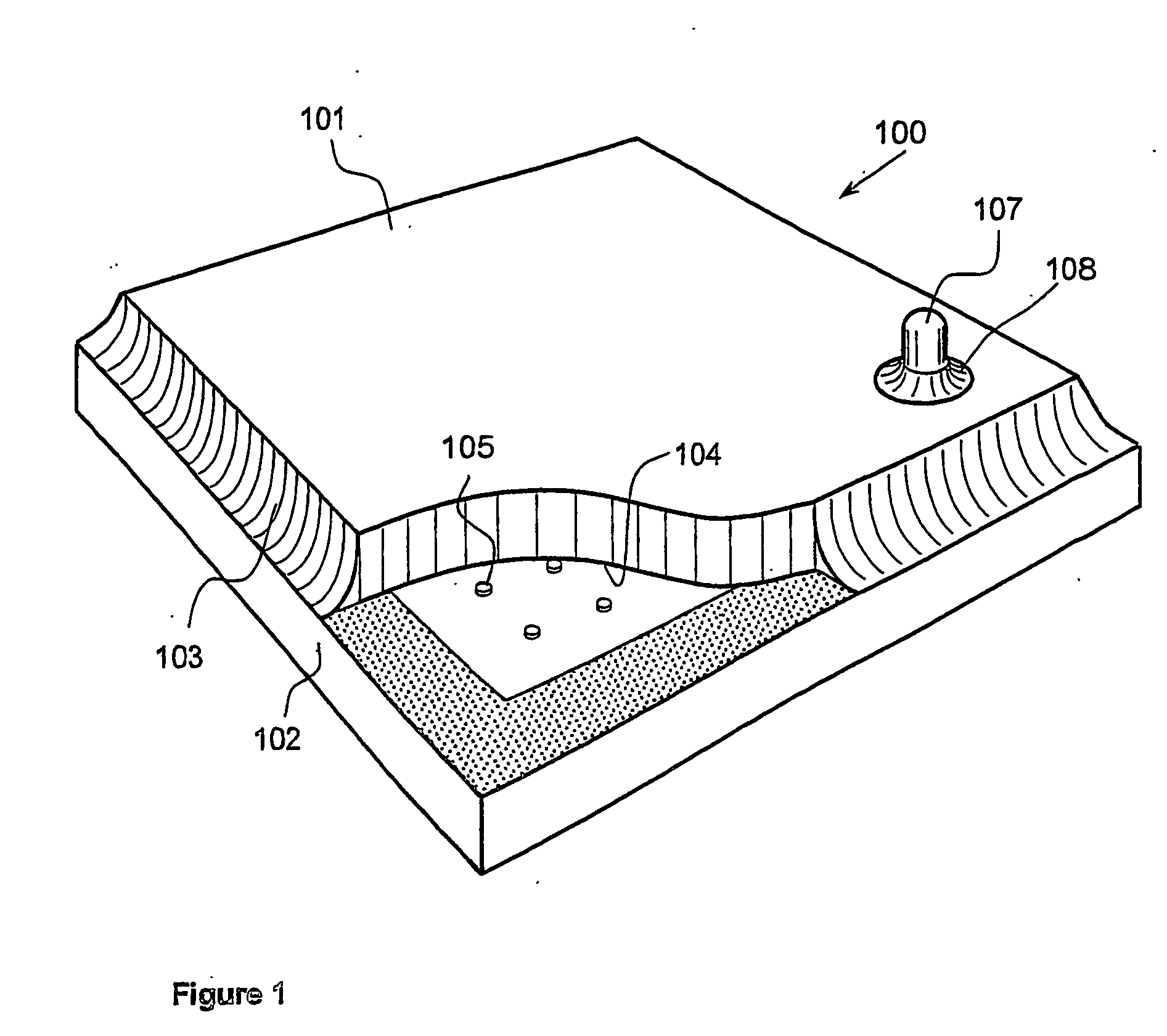
[0052]FIG. 1 illustrates a flat evacuated glass panel 100 which comprises two plane glass sheets 101, 102 that are maintained in spaced-apart face-to-face confronting relationship. The glass sheets are normally composed of soda-lime glass and are interconnected along their edges by a bead 103 of edge-sealing solder glass.

[0053] A chamber 104 is defined by the two glass sheets 101, 102 and these sheets are maintained in spaced relationship by a network or array of support pillars 105. The chamber 104 is evacuated to a level below 10−3 Torr, this providing for gaseous heat conduction through the sheets that is negligible relative to other heat flow mechanisms.

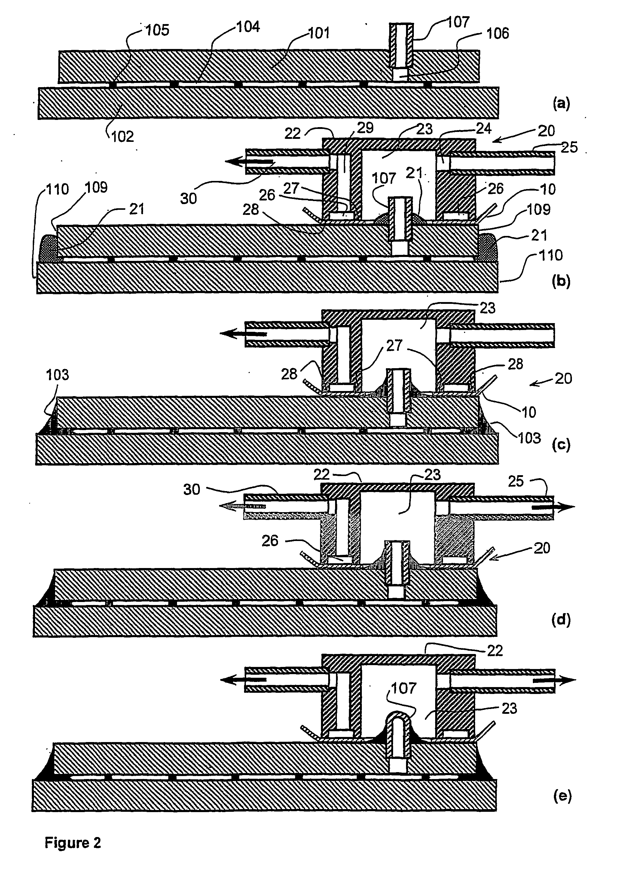
[0054] The glass sheet 101 is formed with an aperture 106 (see FIG. 2), and a glass pump-out tube 107 is positioned to locate within and project outwardly from the aperture 106. The pump-out tube is sealed to the glass sheet by a bead 108 of solder glass. The pump-out tube is sealed following evacuation of the panel as illustra...


PUM


Abstract

A gasket (10) is provided for an evacuation head assembly (20) to evacuate a chamber (104) defined by two glass sheets (101, 102). The gasket (10) may be made from a metal foil such as aluminium and has opposite sealing surfaces (14, 15, 19) that are profiled with a series of fine grooves (17) and wherein the variation in thickness between the sealing surfaces is less than 1 μm.

Description

FIELD OF THE INVENTION [0001] This invention relates to the evacuation of a chamber that is defined (i.e. enclosed) by a glass wall that includes a port through which evacuation is effected. The invention has been developed in the context of evacuated glass panels, such as vacuum glazing and plasma display panels, and the invention is herein described in that context. However, it will be understood that the invention does have broader application, for example including flat panel-formed display devices. BACKGROUND OF THE INVENTION [0002] In one form of vacuum glazing, two plane spaced-apart sheets of glass are positioned in face-to-face confronting relationship and are hermetically sealed around their edges with a low melting point glass that commonly is referred to as solder glass. The space (i.e. chamber) between these sheets is evacuated and the face-to-face separation of these sheets is maintained by a network of small support pillars. In typical situations the glazing may compr...

Claims


Application Information

Patent Timeline
Patent Type & Authority Applications(United States)
IPC IPC(8): F16J15/02E06B3/677
CPCE06B3/6612E06B3/6775Y02B80/24H01J9/385H01J2211/54F16J15/0881Y02A30/249Y02B80/22
Inventor COLLINS, RICHARD EDWARDNG, KWOK LEUNS
Owner THE UNIV OF SYDNEY
Why Eureka
Try Eureka