Microchip, sampling method, sample separating method, sample analyzing method, and sample recovering method

a microchip and sample technology, applied in the field of microchips, can solve the problems of reducing resolution, unable to obtain high-accuracy analysis, and unable to perform high-accuracy analysis, and achieve the effects of reducing resolution, reducing the degree of freedom, and efficient separation or recovery

Inactive Publication Date: 2006-08-10
NEC CORP
View PDF5 Cites 31 Cited by
  • Summary
  • Abstract
  • Description
  • Claims
  • Application Information

AI Technical Summary

Benefits of technology

[0039] For example, in the sample separation method of the invention, the remote operation may be a laser trap (hereinafter also referred to as “optical tweezers”). Thus, the damming portion is irradiated with light, and the complex can securely be held by using the optical tweezers function. In the case where the complex is held in the damming portion by the laser trap, the complexes located on the upstream side of the held complexes are disturbed by the held complexes and cannot pass through the damming portion, and the complexes are deposited in the damming portion. Therefore, the complex can securely be deposited in the damming portion without providing the physical obstacle portion.
[0040] Further, the damming portion can easily be formed at an arbitrary position in the channel after the microchip is produced. Therefore, a degree of freedom is enlarged in designing the microchip, which allows the microchip having the configuration more suitable to the purpose to be obtained. The sample can securely and rapidly be extracted from the carrier from which the sample is extracted by the stimulus and the sample movement can be started.
[0041] As described above, the invention can realize a technology in which the extremely small amount of sample is efficiently separated or recovered by simple operation. Further, the invention can realize a technology in which the extremely small amount of sample is efficiently analyzed.

Problems solved by technology

However, the small amount of sample introduced from the input channel to separation channel can obtain only the extremely small amount of a target component during the separation.
Therefore, the target component having high density cannot be obtained, and sometimes the high-accuracy analysis cannot be performed.
On the other hand, when a width of the input channel is widened to increase the amount of introduced sample, a band width of the sample flowing in the separation channel is widened to decrease resolution, and sometimes the high-accuracy separation cannot be performed.

Method used


Image

  • Microchip, sampling method, sample separating method, sample analyzing method, and sample recovering method
  • Microchip, sampling method, sample separating method, sample analyzing method, and sample recovering method
  • Microchip, sampling method, sample separating method, sample analyzing method, and sample recovering method

Examples


first embodiment

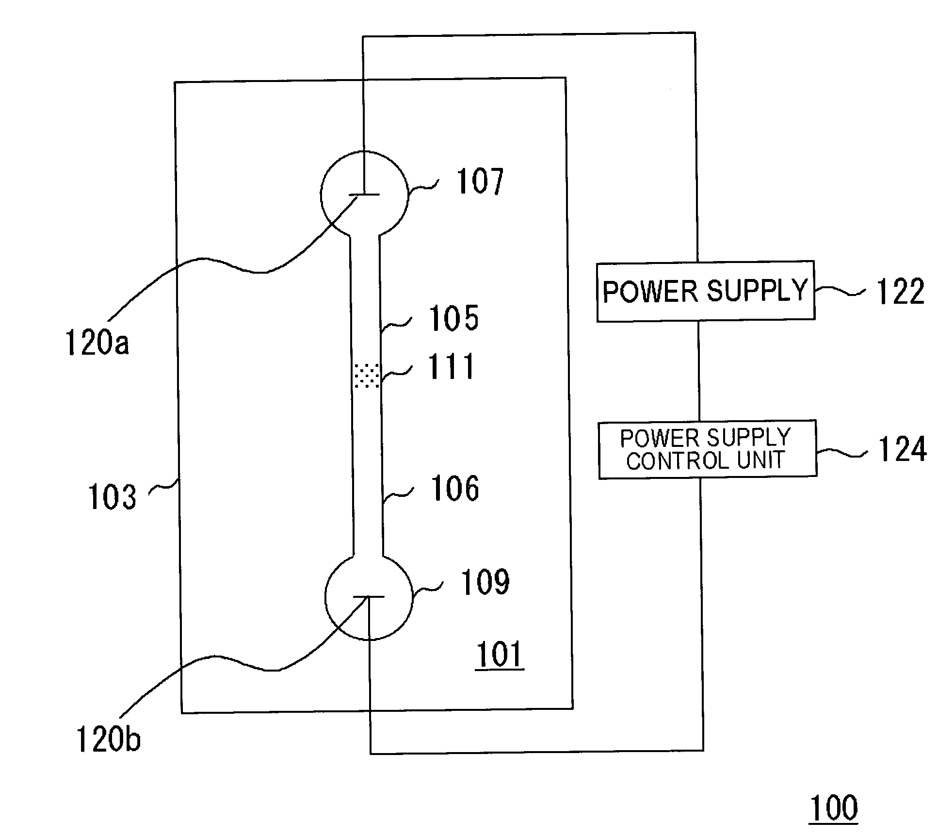
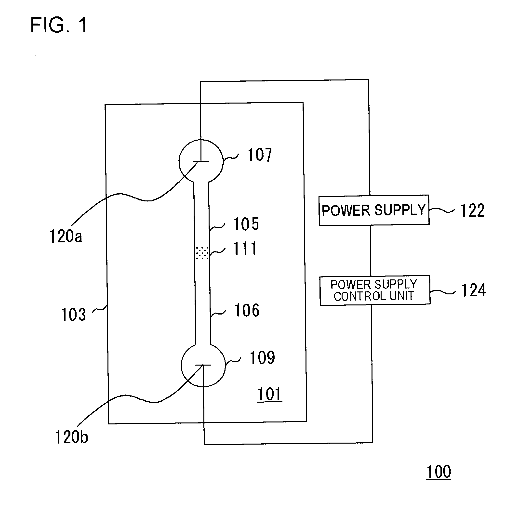
[0063] The present embodiment is about a microchip in which a physical damming member is provided in the damming portion provided in the channel. FIG. 1 is a view showing a configuration in which the microchip of the embodiment is applied to a separation apparatus. A microchip 101 constituting a separation apparatus 100 includes a sample introducing portion 107, first channel 105, a second channel 106, and a sample recovery portion 109. The sample introducing portion 107 is formed on a substrate 103. A damming portion 111 is provided in the first channel 105, and the damming portion stems the sample in a complex state in which a carrier holds the sample. A separation area (not shown) is provided at a predetermined position of the second channel 106.

[0064] The sample is introduced into the sample introducing portion 107 while held by the carrier, that is, being in the complex state, and is moved in the first channel 105. Because the sample cannot pass though the damming portion 111 ...

second embodiment

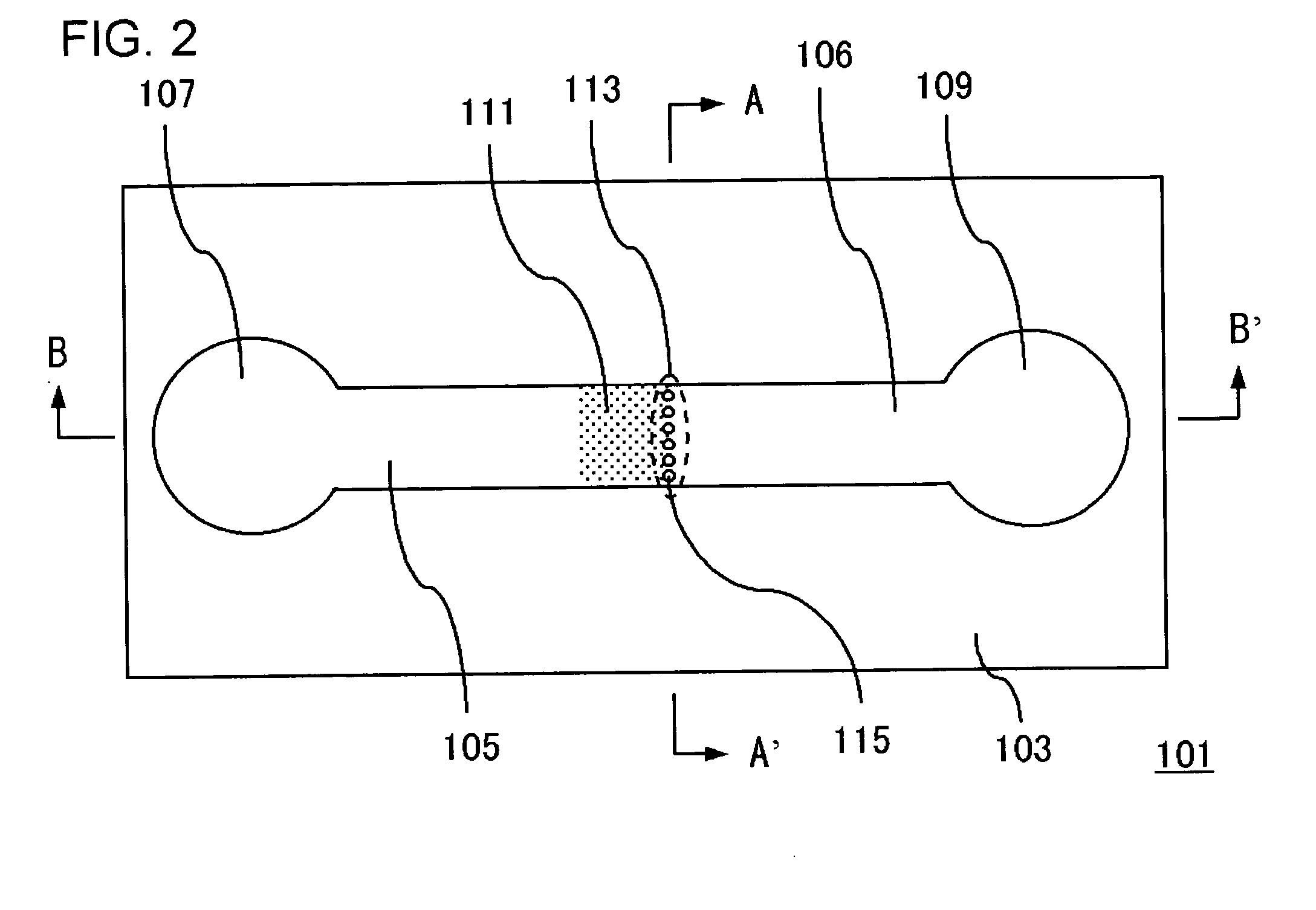
[0127] This embodiment is a mode, in which the micell having a disulfide bond is used and a reducing agent introduced into the first channel 105 triggers the collapse of the sample-carrier complex 119 in the microchip 101 (FIG. 2) described in the first embodiment. The configuration of the microchip according to the embodiment is basically similar to the microchip 101. However, it is not necessary to heat the damming portion 111, so that the heater 117 is not particularly provided.

[0128] When the sample 121 is the polyanion such as DNA, for example, polythiol-polycation-hydrophilic polymer block copolymer can be prepared and used to form the micell involving the sample 121. Since the carrier 123 has the polycationic area, the carrier 123 and the sample which is of the polyanion can form the poly-ion-complex micell. In this case, polythiol should mean the polymer having a monomer unit whose side chain has a —SH group.

[0129] A PEG-polyLys-thiol group introduced polyLys block copolym...

third embodiment

[0131] This embodiment differs from the first embodiment in the configuration of the damming portion 111 of the microchip.

[0132]FIG. 15 is a top view showing the damming portion 111 of a microchip according to the embodiment. Referring to FIG. 15, plural hydrophobic areas 191 are regularly arranged at substantially even intervals in the damming portion 111. The surface of the substrate (not shown) made of quartz or the like is exposed and is formed in the hydrophilic area 192 in the area except for the hydrophobic areas 191. The hydrophobic property of the damming portion 111 is properly controlled by forming the hydrophobic / hydrophilic patterns. A dispersing medium of the sample-carrier complex 119 exists selectively in the upper portion of the hydrophilic area 192, and the upper portion of the hydrophobic area 191 becomes empty.

[0133] As a result, similarly to the columnar bodies 115 in the first embodiment, the hydrophobic area 191 can stem the sample-carrier complex 119 which ...


PUM

PropertyMeasurementUnit
widthaaaaaaaaaa
thicknessesaaaaaaaaaa

Abstract

A sample-carrier complex (119) is introduced into a sample introducing portion (107), and the sample-carrier complex (119) is moved and deposited on a damming portion (111). The damming portion (111) is heated at a stage in which the predetermined amount of sample-carrier complex (119) is deposited on the damming portion (111). A temperature is increased to a predetermined temperature to break down the sample-carrier complex (119) into a sample (121) and a carrier (123). A voltage is applied between the sample introducing portion (107) and a sample recovery portion (109) to cause the sample (121) to pass through a gap between columnar bodies (115) and move into a second channel (106) to perform predetermined separation and analysis or recovery operation.

Description

TECHNICAL FIELD [0001] The present invention relates to a microchip and a method of extracting a sample, a method of separating a sample, a method of analyzing a sample, and a method of recovering a sample therewith. BACKGROUND ART [0002] Recently research and development of microchips in which a function of separating or analyzing substances derived from living organism is included on a chip are actively performed (Patent Document 1). In these microchips, a fine separation channel is provided by using a fine processing technology, and an extremely small amount of sample can be introduced into the microchip to perform separation and analysis. [0003] Approaches that an electrophoresis technology is introduced are proposed in a technical field in which the microchip is utilized for proteomics and genomics researches. Protein and peptide are separated by the electrophoresis and are recovered from gel to perform the analysis. In the electrophoresis in which the microchip is used, as sho...

Claims


Application Information

Patent Timeline
Patent Type & Authority Applications(United States)
IPC IPC(8): G01N1/10B01D57/02B01L3/00G01N1/40G01N27/447G01N35/08
CPCB01D57/02B01L3/502707B01L3/502746B01L3/502753B01L3/502784B01L2200/0668B01L2300/0681B01L2300/0816B01L2400/0415B01L2400/0454G01N1/40G01N27/44743G01N35/08
Inventor SANO, TORUBABA, MASAKAZUIIDA, KAZUHIROKAWAURA, HISAOIGUCHI, NORIYUKIHATTORI, WATARUSOMEYA, HIROKO
Owner NEC CORP
Why Eureka
Try Eureka