Uplink transmission power control in a CDMA base station

a transmission power control and cdma technology, applied in power management, multiplex communication, sustainable buildings, etc., can solve the problems of reducing the quality of communication, and increasing the amount of interference in the entire cell. , to achieve the effect of not increasing the amount of interference in the entire cell

Inactive Publication Date: 2006-08-17
NEC CORP
View PDF4 Cites 11 Cited by
  • Summary
  • Abstract
  • Description
  • Claims
  • Application Information

AI Technical Summary

Benefits of technology

[0027] It is an object of the present invention to provide a CDMA base station and uplink transmission power control method, wherein the amount of interf

Problems solved by technology

However, since it is difficult to maintain perfect orthogonality among all the spread codes being used, the practical situation is that the spread codes are not perfectly orthogonal to each other but have correlated components with other codes.
For this reason, these correlated components act as interference components against individual communications, causing degradation of communication quality.
Since interference components are caused in this way, the interference components are compounded with the number of communications.
Accordingly, if the transmission powers of all mobile stations are set at a fixed level, the radio waves from mobile stations near the base station are too strong, so that the signals from mobile stations remote from the base station are greatly subjected to interferences thereby, causing the so-called near-far problem.
However, since SIR is a signal interference power ratio, if the amount of interference increases, then SIR is lowered, so that the base station performs control to direct the mobile station to increase the transmission power.
This control is performed on all the mobile stations, tending to increase the amount of interference in the entir

Method used


Image

  • Uplink transmission power control in a CDMA base station
  • Uplink transmission power control in a CDMA base station
  • Uplink transmission power control in a CDMA base station

Examples


Embodiment Construction

[0034] The present invention is premised on the assumption that a base station and mobile stations perform wireless communication using CDMA scheme and that closed-loop uplink transmission power control is performed between the base station and mobile stations.

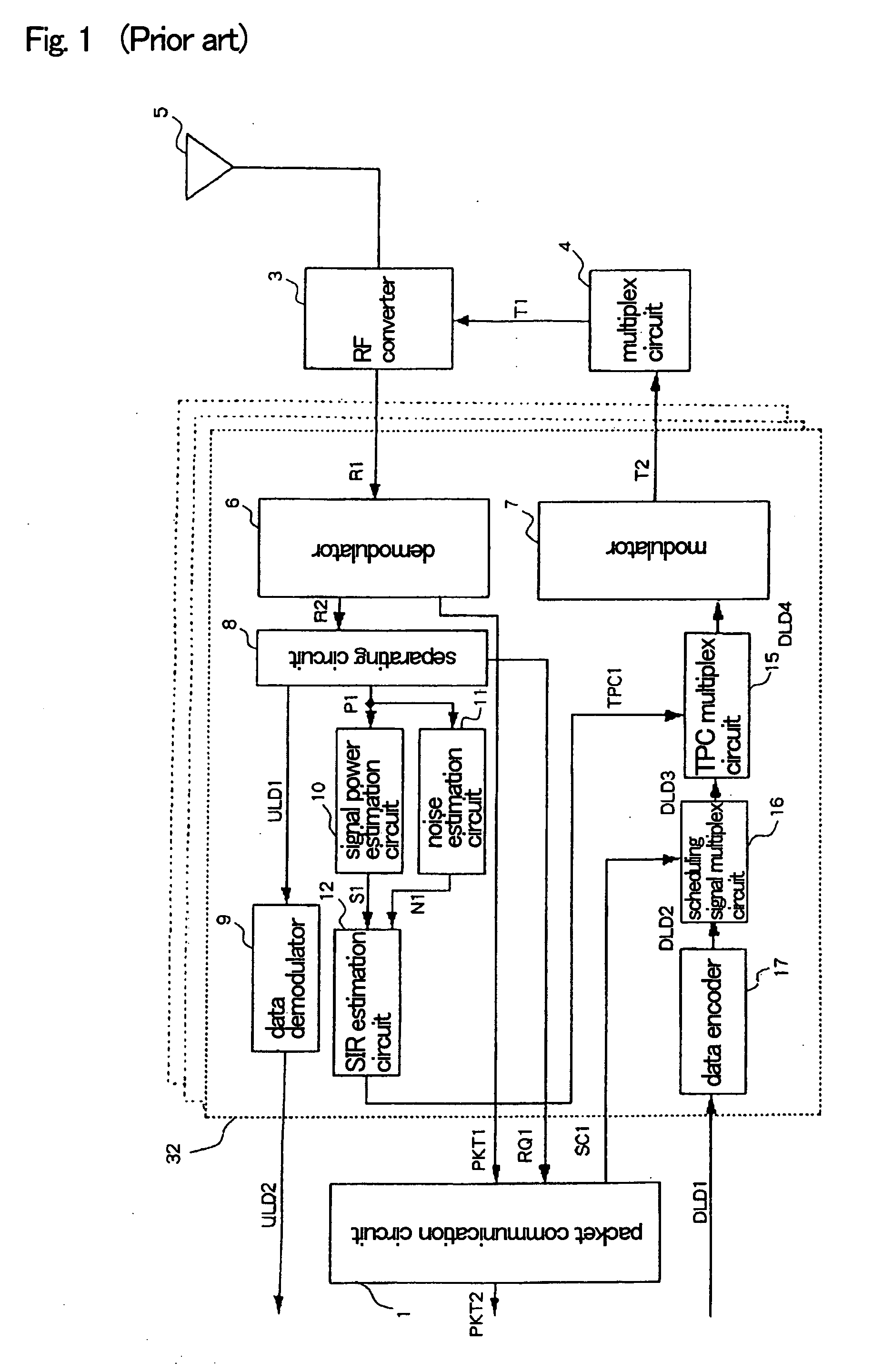
[0035] Referring to FIG. 3, there is shown a CDMA base station system according to an embodiment of the present invention, comprising packet communication circuit 1, a plurality of CDMA modulating and demodulating circuits 2, RF converter 3, multiplex circuit 4, and antenna circuit 5. In FIG. 3 the same components as those in FIG. 1 are assigned the identical reference numerals and hence their descriptions are omitted.

[0036] Each CDMA modulating and demodulating circuit 2 includes demodulator 6, modulator 7, separating circuit 8, data decoder 9, signal power estimation circuit 10, noise estimation circuit 11, SIR estimation circuit 12, noise comparator 13, TPC bit generating circuit 14, TPC multiplex circuit 15, scheduling s...


PUM


Abstract

A CDMA base station is disclosed that prevents significant increase in the amount of interference within an entire cell even when there exist in the cell mobile stations that perform high-speed packet communication. The CDMA base station comprises a noise estimation circuit, a noise comparator and a TPC bit generating circuit. The noise comparator receives noise power N1 estimated by the noise estimation circuit, compares the noise power N1 with a threshold N2 for interference supplied from packet communication circuit 1 and outputs the result of comparison N3 to the TPC bit generating circuit. The TPC bit generating circuit sets TPC2=0, outputting TPC command TPC2 to direct a TPC multiplex circuit to reduce the transmission power, without using TPC command TPC1 from a SIR estimation circuit when the increase in the transmission power of a mobile station that is performing high-speed packet transmission within a fixed period of time has exceeded the threshold for the increase or when the amount of interference in the entire cell has exceeded the threshold for the amount of interference.

Description

BACKGROUND OF THE INVENTION [0001] 1. Field of the Invention [0002] The present invention relates to a CDMA base station and a method of performing uplink transmission control (TPC: Transmission Power Control) to control uplink transmission power from mobile stations. [0003] 2. Description of the Related Art [0004] Recently, as communication technologies used for mobile communications systems, much attention has been focused on CDMA (Code Division Multiple Access) communication technology, which is robust against interference and disturbance. This CDMA communication technology is a communication scheme in which on the transmitter side a user signal to be transmitted is spread by spread coding and transmitted and on the receiver side the user signal is despread using the same spread coding as the former spread coding to obtain the original user signal. [0005] In the CDMA communication, a plurality of transmitter sides perform spread by using different spread codes that are orthogonal...

Claims


Application Information

Patent Timeline
IPC IPC(8): H04B7/00H04J13/00H04W52/04H04W52/08H04W52/24
CPCH04W52/08H04W52/146H04W52/221H04W52/243H04W52/247H04W52/248Y02B60/50
Inventor MURAOKA, SHINYA
Owner NEC CORP
Why Eureka
Try Eureka