Modular intake system

a module-type, intake system technology, applied in the direction of hose connection, combustion-air/fuel-air treatment, bends, etc., can solve the problems of reducing power and fuel economy, affecting the performance of the engine, and reducing efficiency and complete combustion process, so as to improve engine performance.

Inactive Publication Date: 2006-08-24
SPECTRE INDS
View PDF16 Cites 37 Cited by
  • Summary
  • Abstract
  • Description
  • Claims
  • Application Information

AI Technical Summary

Benefits of technology

[0014] In one embodiment, two modular intake components may be joined together with a separate collar structure. A collar adapter may be implemented to permit a single collar structure to function with multiple intake component sizes (e.g., tube widths). In other embodiments, the ends of two modular components may be configured with interlocking ridges that allow for the two modular components to lock together at one or more angular orientations by application of a twisting movement.
[0015] In o

Problems solved by technology

The temperature of the air obtained via the intake system affects the performance of the engine, because it affects the density of the air in the gasoline-air mixture.
With a relative increase in temperature, the decreased input air density translates to a less efficient and less complete combustion process (e.g., due to the decreased availability of oxygen), as well as decreased post-combustion gas volume, resulting in reduced power and fuel economy.
Unfortunately, many air intake systems, particularly OEM (original equipment manufacturer) systems, have poor heat reflection characteristics, permitting the heat from the engine to penetrate the intake structure and raise the temperature of the ambient air drawn through the system.
In addition, restriction of the air flow through the intake system can decrease engine performance because less air volume passes through the engine per unit time.
Since original equipment manufacturer's air intake systems may be more restrictive, some operators modify their engines by replacing the stock intake system with a freer flowing aftermarket cold air intake system to gain horsepower, torque, and throttle response.
In practice, some of these prior art air intake systems do not always fit perfectly for the specific automobile for which they were designed.
For example, the addition of other aftermarket components may have encroached upon the space normally taken by the intake system.
Prior art aftermarket air intake systems can be problematic for the op

Method used


Image

  • Modular intake system
  • Modular intake system
  • Modular intake system

Examples


Embodiment Construction

[0035] A modular air intake system for an automobile engine is described. In the following description, numerous specific details are set forth to provide a more thorough description of embodiments of the invention. It will be apparent, however, to one skilled in the art that the invention may be practiced without these specific details. In other instances, well known features have not been described in detail so as not to obscure the invention.

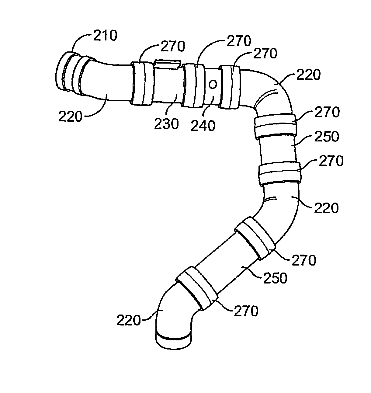
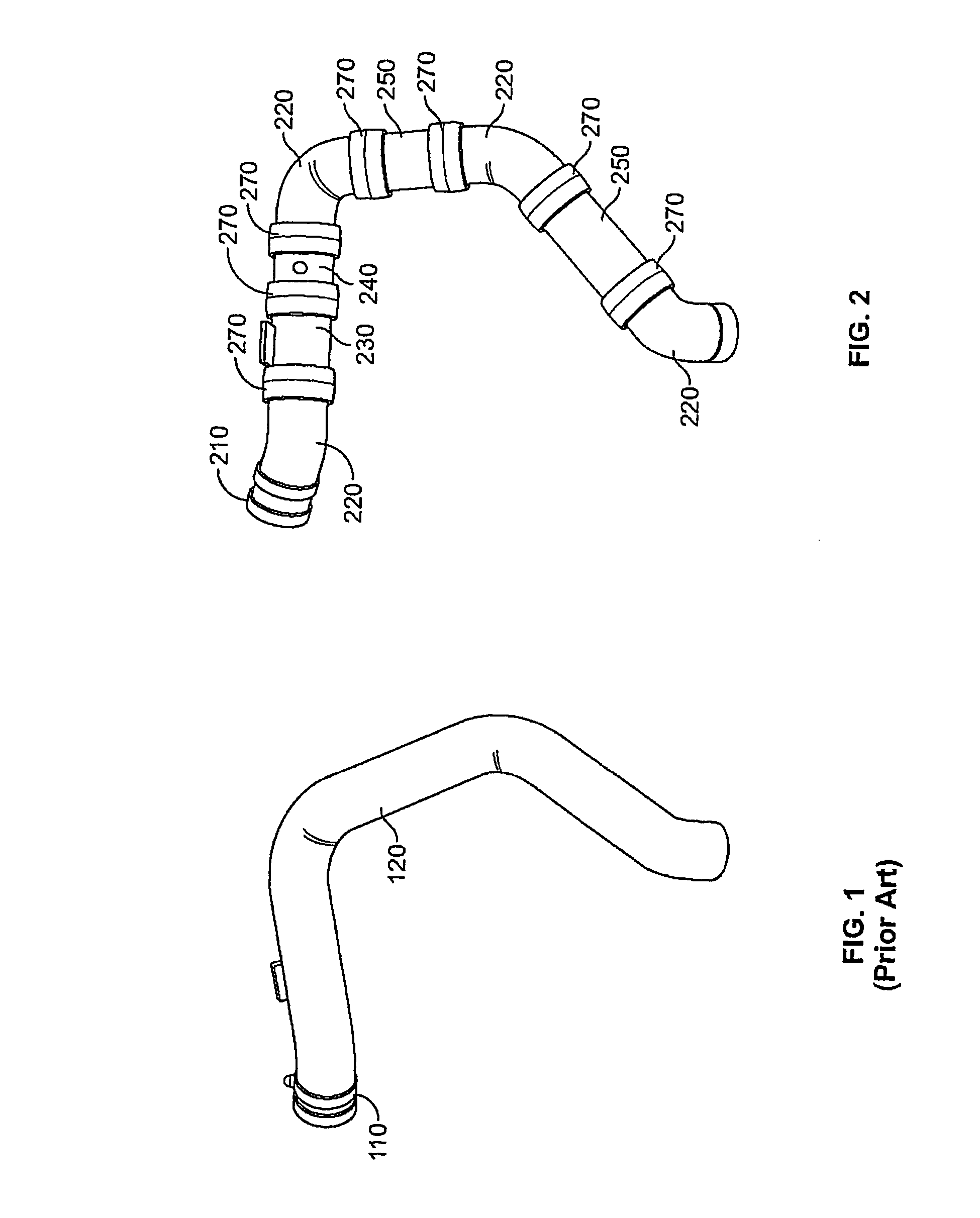
[0036] In one or more embodiments of the present invention, modular components may be assembled into one of many possible configurations to form an air intake system to fit any one of most automobile models. The modular intake system may be configured, for example, to provide less restricted airflow to the automobile engine, an alternate / additional intake path, and / or a more visually appealing engine compartment (e.g., for show purposes).

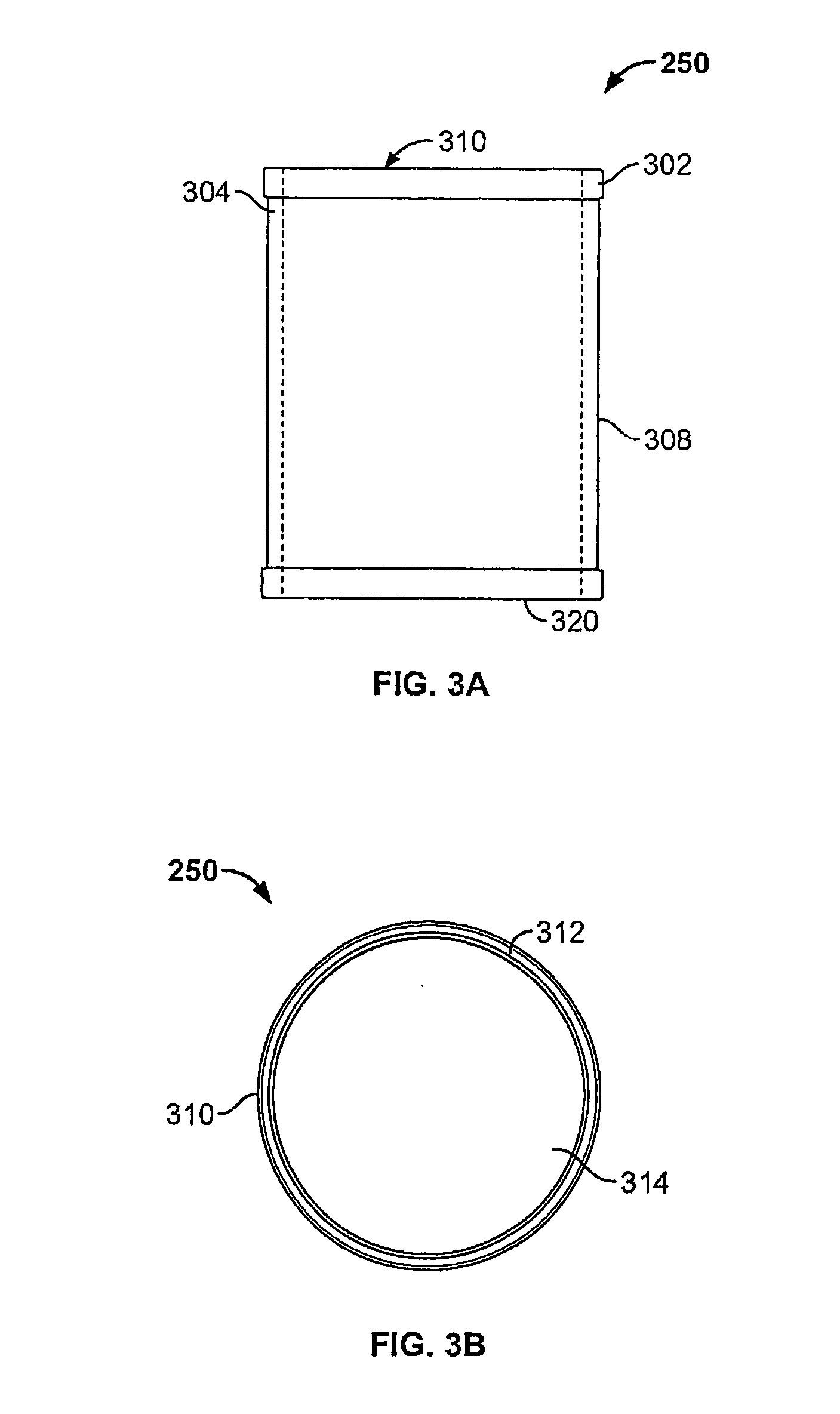
[0037] In one or more embodiments, components of the air-intake system may be manufactured from a combin...


PUM

PropertyMeasurementUnit
Lengthaaaaaaaaaa
Structureaaaaaaaaaa
Metallic bondaaaaaaaaaa

Abstract

A modular air intake system is presented. The system comprises a variety of modular components that may be coupled together to form a desired air intake system configuration for an automobile engine. Each modular component has a plastic structure with chrome plating, resulting in improved insulation and heat reflection characteristics for better engine performance. An intake system may be configured to fit into virtually any automobile engine compartment, because the components may be coupled in any combination, and the angular connection relationship between any two components is adjustable. A locking split-collar may be used to lock the junctions between modular components to provide a fixed configuration.

Description

FIELD OF THE INVENTION [0001] This invention relates to the field of automotive apparatus. More specifically, the invention relates to intake systems for automobile engines. BACKGROUND [0002] The vast majority of current automobile engines are internal combustion engines that operate on a fuel comprising a mixture of gasoline and air. The combustion of the fuel is used to drive an array of pistons or rotors. Through a variety of mechanical means, the combined kinetic energy of the piston or rotor array is applied to the drive shaft of the automobile in a controlled manner to rotate the wheels and move the automobile. [0003] More specifically, within a typical automobile engine, the gasoline-air mixture is introduced to a cylinder chamber, within which the mixture is compressed by the inward motion (or “stroke”) of a piston or rotor. At an optimal point in the “compression stroke,” a spark plug creates an electrical spark within the chamber, igniting the fuel. The combustion of the f...

Claims


Application Information

Patent Timeline
IPC IPC(8): F02M35/10F16L11/14B21K3/00
CPCF02M35/10137F02M35/10144F02M35/10321F02M35/10347Y10T29/49231F02M35/10373F16L33/04F16L41/023F16L43/00F02M35/10354
Inventor ROSENBAUM, AMIR
Owner SPECTRE INDS
Why Eureka
Try Eureka