Spray for fluent materials

Active Publication Date: 2006-08-24
CONFLUENT SURGICAL
View PDF71 Cites 129 Cited by
  • Summary
  • Abstract
  • Description
  • Claims
  • Application Information

AI Technical Summary

Benefits of technology

[0009] An angle between two openings may be measured by fitting a plane to each opening and measuring the angle formed by the intersection of the two planes. Thus, two openings may define the angle between them when the openings are positioned relative to each other so that there is an angle formed by the intersection of the two planes. Thus two openings that were perpendicular to each other would have an angle of 90 degrees between them. The angle between two flat surfaces is readily measured when every point of an opening falls in a single plane; for example, an opening on a flat surface is disposed in one plane. When an opening is made in a curved surface, however, it is necessary to fit a plane to the opening. The fit may be accomplished using mathematical techniques known to persons of skill in these arts. Without being bound to a particular theory of action, it is believed that the angled tip creates a low-pressure zone between spraying fan patterns of two or more components, thereby drawing the components together in the air stream beyond the tip and improving their mixing. The angled tip also creates a wall or divider between adjacent lumen openings, thereby preventing cross-talk between precursors before they enter the air stream. Further, an angled tip may be more precise and deliver a higher quality gel over the course of an application.
[0010] An advantage of placing the openings adjacent to each other is that such placement facilitates the mingling of compositions that flow through the openings. Openings that are adjacent to each other are typically separated only by a thickness of the material that defines the openings. For example, two needles may be placed adjacent to each other, with their exteriors touching. The openings may be further separated and still be conside

Problems solved by technology

Applicants have determined that when attempting to use a propellant to apply materials in a laparoscopic setting, which typically is insufflated with a gas to provide a wider field of view for the clinician, the propellant can result in excessive distension of the tissue surrounding the operative site.
In addition, in the above laparoscopic context, when a sprayer is first introduced into the surgical site, for example, via a trocar tube, the ambient pressure may inadvertently charge the supply reservoirs (if the supply line

Method used


Image

  • Spray for fluent materials
  • Spray for fluent materials
  • Spray for fluent materials

Examples


example 1

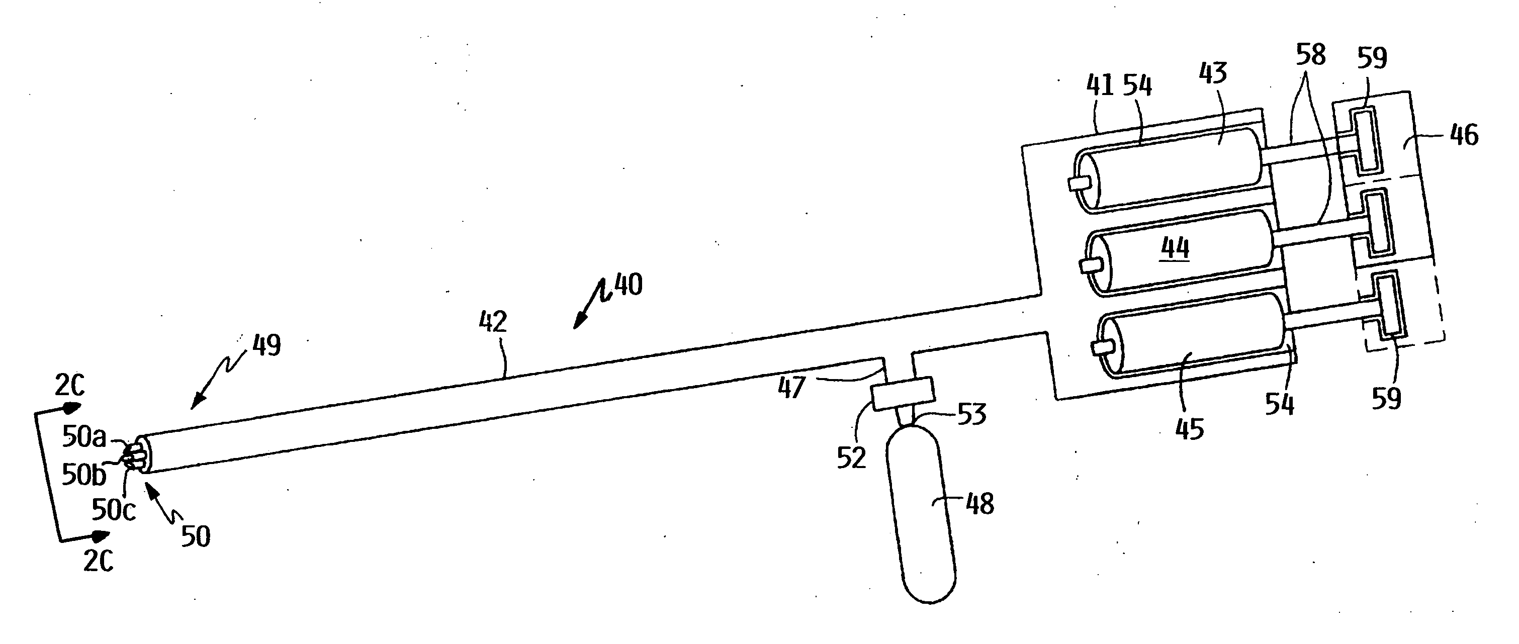
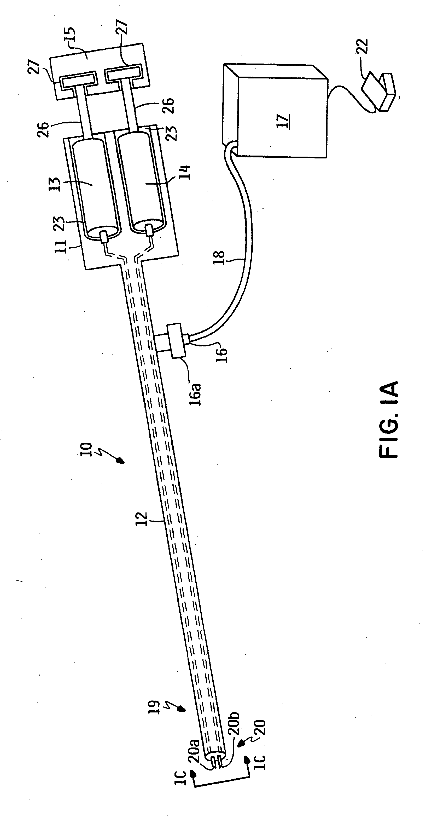
[0104] Sprayer 10 of FIG. 1 is used in conjunction with aqueous solutions of crosslinkable monomers. Solution 1, consisting of a 10% solution of a polyethylene glycol diacrylate (M.W. 3,000 Da, purchased from Shearwater Polymers, Huntsville, Ala.) dissolved in normal saline (pH 5-6) and containing 500 ppm of hydrogen peroxide is drawn up in syringe 13, preferably a 5 cc syringe. Solution 2, consisting of a 10% solution of a polyethylene glycol diacrylate dissolved in normal saline (pH 5-6) and containing 5000 ppm of ferrous sulfate peroxide, is drawn up in syringe 14, also a 5 cc syringe. Syringes 13 and 14 are individually loaded in compartments 23, and are coupled to conduits 24 and 25 and actuator 15.

[0105] Airflow from a regulated source of compressed air (an air compressor such as those commercially available for airbrushes) is connected to the sprayer 10 using a piece of tubing. When actuator 15 is depressed, a steady spray of the two liquid components will be observed. When ...

example 2

[0106] A sprayer as in sprayer 10 of FIG. 1 was mounted in a rigid system in a horizontal position for a horizontal spray test. The sprayer was essentially identical to sprayer 10, except that the gas flow outlets and conduits were arranged as depicted in FIG. 6A, 6B. The angle 511, and was about 90 degrees, sheath 512 was made of plastic, and encompassed conduits 504, 506, to define gas outlet 514. Gap 516 was about 0.7 mm.

[0107] The tip of each sprayer was a distance of 2 cm from the target location, a vertical mylar sheet. In each of the syringes 13 and 14 was placed 1 mL of DuraSeal® sealant. Plungers 26 were depressed to dispense 0.2 mL (0.1 mL per syringe). The sprayer 10 was left to stand for 30 seconds. Then an additional 0.2 mL (0.1 mL per syringe) increment was delivered. This was repeated until the entire polymer was delivered in 0.2 mL increments with 30 seconds of standing between each application. The same procedure was followed for sprayer 10 that contained a straigh...

example 3

[0110] Sprayers were tested to determine the air flow required to achieve both good mixing and good material formation from the compositions. Sprayers as in Example 2 were mounted vertically in a rigid fixture suspended 4 cm form a target of mylar. The sprayers were connected to an air source with a regulator, and the mass flow of the air was adjusted to range between 0.2 to 1.0 liters / minute. A total volume of 0.4 ml of the material formed from the precursors was deposited on the target at each flow rate. The pattern of material formed on the target was observed. At 1.0 l / min, the material was deposited in a volcano-shape, i.e., a circle with relatively more material deposited around the edges of the circle. At rates below 0.4 l / minute, the applicator tended to clog. The 0.6 ml / minute rate made a pattern that was relatively more consistent in thickness and quality compared to 0.8 ml / minute rate, which showed a more significant volcano effect.


PUM


Abstract

Certain embodiments relate to a sprayer or other medical apparatus for applying a biocompatible coating in situ. Such an apparatus may have a first conduit connected to a first exit opening and a second conduit connected to a second exit opening to deliver a first composition through the first conduit and a second composition through the second conduit to mix the first composition and the second composition outside both the first conduit and the second conduit. The first composition may be, e.g., a precursor to a material formed after the mixing of the first composition and the second composition. The first exit opening and the second exit opening may be approximately adjacent to each other and define an angle that is less than about 140 degrees.

Description

FIELD OF THE INVENTION [0001] Certain aspects of the field of the invention relate generally to methods and apparatus for forming biocompatible materials, and, more particularly, to apparatus and methods using an angled tip sprayer for delivering two liquid components that form hydrogels upon mixing. BACKGROUND OF THE INVENTION [0002] Often during surgery, tissue may be traumatized or compromised such that it needs to be temporarily supported or isolated during the wound healing period. Materials that may be used as tissue sealants also may be used to temporarily support tissue and to seal leaks from tissue until the tissue heals. Tissue sealants that perform these functions are well known in literature and include a variety of natural and synthetic sealants including fibrin sealants, cyanoacrylate based sealants, and other synthetic sealants and polymerizable macromers. [0003] Various types of devices have been developed that address many aspects of spraying technologies to deliver...

Claims


Application Information

Patent Timeline
IPC IPC(8): A61M5/00B67D5/52B67D7/70
CPCA61B2017/00495A61B17/00491
Inventor CAMPBELL, PATRICK KENNETHDRISCOLL, ARTHUR J.GUEST, TOM
Owner CONFLUENT SURGICAL
Why Eureka
Try Eureka