Magnetic resonance spectrometer

a magnetic resonance spectrometer and magnetic resonance technology, applied in the field of magnetic resonance instruments, can solve the problems of large volume, high cost and bulky of conventional spectrometers, and no superconducting magnet can produce such a homogeneous field. achieve the effect of efficient and reliable preparation

Inactive Publication Date: 2006-09-07
ELECTROPLATED METAL SOLUTIONS
View PDF7 Cites 12 Cited by
  • Summary
  • Abstract
  • Description
  • Claims
  • Application Information

AI Technical Summary

Benefits of technology

[0024] It is yet another object of the present invention to produce a ferroelectric single crystal consisting essentially of the potassium tantalate and the alkali m

Problems solved by technology

As a result, conventional spectrometers are relatively expensive and bulky, and are typically used as stationary equipment in research laboratories.
Although Nuclear Magnetic Resonance (NMR) devices, due to frequency range lower relative to EPR, have a radio frequency (RF) coil instead of the cavity as the resonator, fundamental dependencies remain between the resonator size and the device capabilities, complexity, size, and cost.
NMR spectrometers have now become very complex instruments capable of performing sophisticated experiments.
On its own, no superconducting magnet can produce such a homogeneous field.
Modern spectrometers might have up to 40 different shim coils, so adjusting them is a very

Method used


Image

  • Magnetic resonance spectrometer
  • Magnetic resonance spectrometer
  • Magnetic resonance spectrometer

Examples


example 1

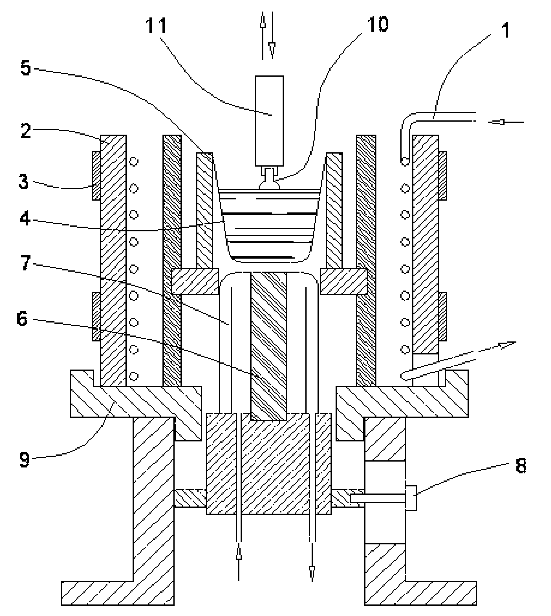
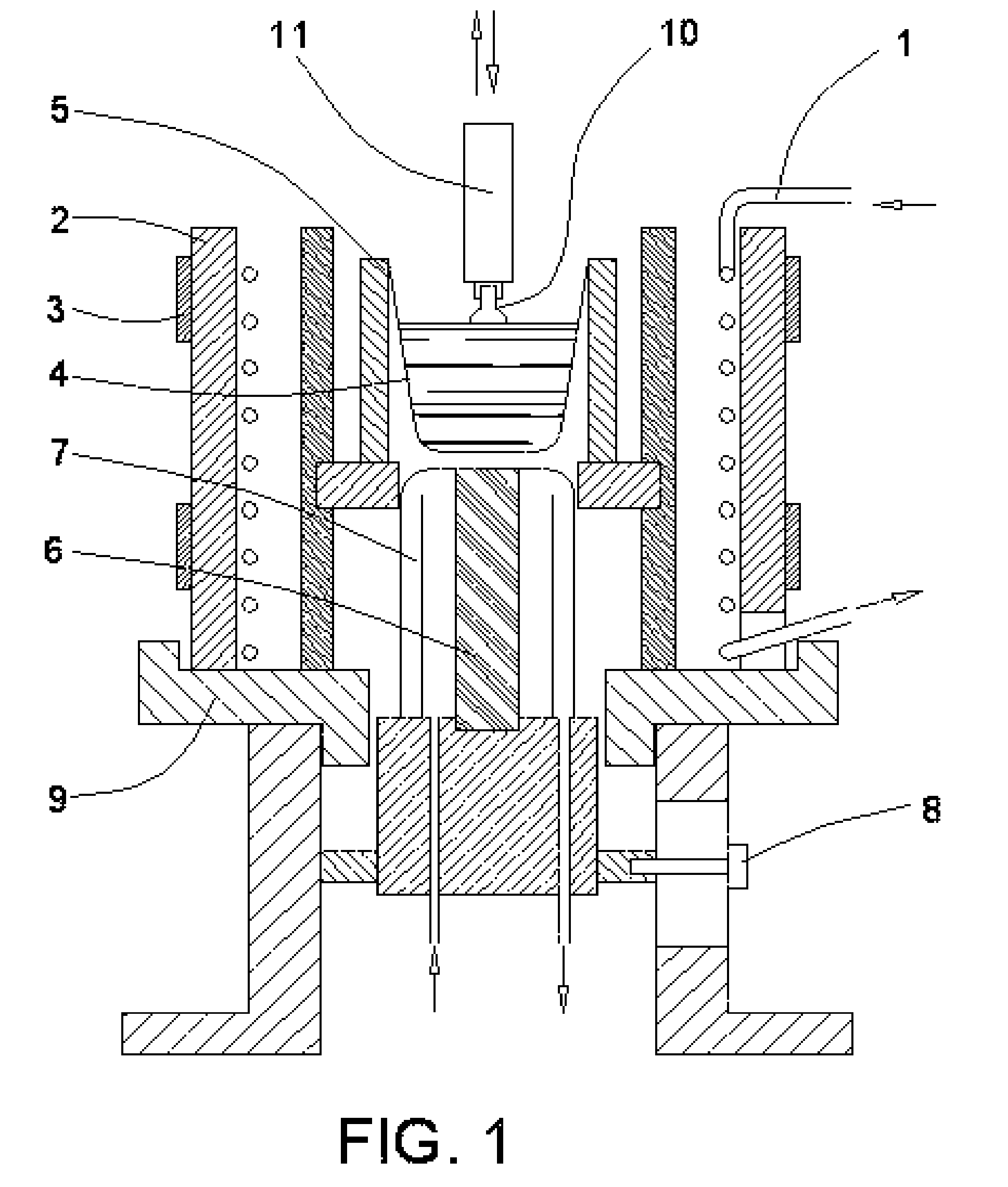
[0056] In one particular instance, the process was carried as follows. Super pure grade of the potassium carbonate K2CO3 and the lithium carbonate Li2CO3 and a tantalum foil of analytically pure grade were used. The foil was cut in about 2 mm wide pieces, placed in a quartz tube connected to an oxygen source, heated to above 850° C., and held at this temperature for 2.5 hours with the oxygen flow of about 0.1 m3 / h. After the cooling, the tantalum oxide Ta2O5 was ground in an agate mortar, separately weighted, placed together with other components in a mass proportion of 30.94% K2CO3, 0.26% Li2CO3, and 68.8% Ta2O5, and thoroughly mixed. Then the mixture was placed in the apparatus (FIG. 1). The crucible was 40 mm in diameter and 50 mm high and initially covered with a platinum lid having a T shape slot. The mixture was heated to 1000±30° C. and held for 5 hours at this temperature. The synthesis of K0.98Li0.02TaO3 is illustrated in a equation:

343K2CO3+15Li2CO3+250Ta2O5→500K0.98Li0.0...

example 2

[0058] In this instance, also, super pure grade of the potassium carbonate KCO3 as well as tantalum and niobium foils of analytically pure grade were used. The tantalum and niobium oxides were prepared under similar to above described conditions. Mass proportion of components was 32.1% K2CO3, 12.2% Nb2O5, and 55.7% Ta2O5. The synthesis of KNb0.2Ta0.8O3 is illustrated in a equation:

7K2CO3+4Ta2O5+Nb2O5→10KNb0.22K2O+7CO2.

[0059] It was established that, when the crucible used for the process was previously used for the example 1 process, a small amount of lithium is present in the melt. This phenomenon was exploited here to have the crystal doped with the lithium. The crystal was grown at the rate of about 1.5 mm / h with the melt cooled down at the rate of about 8° C. / h. The size of the crystal was approximately 4.5 mm square and 11 mm long. The crystal composition was K0.9998Li0.0002Nb0.2Ta0.8O3.

[0060] The crystals produced according to various embodiments of the present invention we...


PUM

PropertyMeasurementUnit
Fractionaaaaaaaaaa
Fractionaaaaaaaaaa
Fractionaaaaaaaaaa

Abstract

EPR spectrometer comprising a ferroelectric single crystal resonator, a rectangular channel with holes in its narrow sides for inserting a sample and wires, a permanent magnet with planar poles, and a coil within the channel connected through the holes by the wires with a modulation source and a NMR spectrometer comprising a magnet, a probe with means for transmitting a radio frequency magnetic pulse and detecting NMR signal, and a ferroelectric single crystal resonator. A ferroelectric single crystal consisting essentially of potassium tantalate and the alkali metal substituting from about 1% to 3% of potassium or a group (V) metal substituting in part for tantalum, having cubic form of perovskite crystalline structure, and essentially free of impurities and defects is also disclosed.

Description

[0001] This application is a continuation-in-part of our co-pending application Ser. No. 10 / 605251, filed Sep. 18, 2003, now abandonedFIELD OF INVENTION [0002] This invention generally relates to the field of magnetic resonance instruments, such as EPR and NMR spectrometers. This invention also relates to the field of fabrication and use of ferroelectric single crystal resonators, in particular, to single crystal microwave resonators including, or consisting essentially of, potassium tantalate and methods for preparation and use thereof. BACKGROUND OF INVENTION [0003] Electron Paramagnetic Resonance (EPR) is widely employed in various applications in the fields of physics, chemistry, medicine and biology. Historically, EPR was used primarily to study samples doped with paramagnetic ions, rather than substantially pure samples. In order to study the samples whose physical properties are unaffected by dopant impurities, particularly samples of materials with low concentration of param...

Claims


Application Information

Patent Timeline
IPC IPC(8): G01V3/00C04B35/495C30B15/00C30B29/30H03H2/00
CPCC04B35/495C04B2235/3201C04B2235/3203C04B2235/3251C04B2235/768C30B15/00C30B29/30H03H2/001H03H2/00G01V3/14
Inventor GEIFMAN, ILIAGOLOVINA, IRINA SERGEEVNA
Owner ELECTROPLATED METAL SOLUTIONS
Why Eureka
Try Eureka