Optical film, liquid crystal panel including the same and liquid crystal display

a liquid crystal display and optical film technology, applied in the direction of instruments, polarising elements, transportation and packaging, etc., can solve the problems of reducing display characteristics, thick and heavy obtained display, and difficult to achieve uniform alignment in a wide area, and achieve low solvency, high solvency, low solvency

Inactive Publication Date: 2006-09-14
NITTO DENKO CORP
View PDF8 Cites 21 Cited by
  • Summary
  • Abstract
  • Description
  • Claims
  • Application Information

AI Technical Summary

Benefits of technology

[0010] The solvency of a solvent with respect to a polymer is generally known. For example, the solvency relationship between N,N-dimethylacetamide, cyclopentanone, ethyl acetate and MIBK is “N,N-dimethylacetamide>cyclopentanone>ethyl acetate>MIBK.” On the other hand, the birefringence in the thickness direction of the non-liquid crystal polymer varies depending on the kinds. It is known that the linearity and rigidity of the molecular skeleton increases with an increase in the birefringence in the thickness direction, making the non-liquid crystal polymer very difficult to dissolve in the solvent as described above. Therefore, in order to dissolve the non-liquid crystal polymer having a high birefringence in its thickness direction, it is well-known that a solvent having a high solvency such as N,N-dimethylacetamide is indispensable. Under such circumstances, the inventors of the present invention have carried out a keen study and found out a non-liquid crystal polymer that is soluble in a nonpolar MIBK with a very low solvency, even having a high birefringence in the thickness direction, namely, Δnxyz of 0.03 or higher. The inventors of the present invention found for the first time that a non-liquid crystal polymer is soluble in a MIBK with a low solvency, in spite of the fact that the solvent has to have a high solvency in order to dissolve a non-liquid crystal polymer whose birefringence in the thickness direction is high as described above. Then, by using these non-liquid crystal polymer and MIBK, even when a solution of the non-liquid crystal polymer is applied to a base such as a TAC film, the base is not eroded by MIBK, which is the solvent, because MIBK has a low solvency in spite of the fact that the non-liquid crystal polymer can be dissolved in MIBK sufficiently. Consequently, even when a birefringent layer is formed on the base as described above, the problem in external appearance such as cloud in the resultant laminate or cracks in the base is solved. From the above, in accordance with the producing method of the present invention, even in the case of using a non-liquid crystal polymer having a birefringence in its thickness direction as high as Δnxyz of 0.03 or higher, it is possible to obtain a laminate of a base and a birefringent layer formed on the base without causing any problem in external appearance. An optical film including such a laminate can achieve excellent display characteristics even when mounted on various image display apparatuses such as a liquid crystal display.

Problems solved by technology

However, since these stretched films have an extremely large thickness of about 25 to 100 μm and further achieve only a small retardation value in a narrow range, they have to be laminated repeatedly over each other for use as a retardation plate with sufficient characteristics.
Therefore, in the case of mounting such a retardation plate on a liquid crystal display, there has been the following problem.
That is, in spite of the fact that reduction in thickness and weight of liquid crystal displays is desired, the obtained display is thick and heavy and has reduced display characteristics due to optical axis displacement or decrease in transmittance caused by laminating the films.
However, since the uniformity of the liquid crystalline compound is dependent on the kinds, uniformity and treatment conditions of the alignment layer or alignment film and susceptible to a surrounding environment, inclination irregularity and alignment irregularity occur easily, leading to a problem that the uniform alignment is extremely difficult to achieve in a wide area.
Further, since many liquid crystalline compounds are not very soluble in organic solvents, limited kinds of solvents having a high solvency need to be used, leading to a problem that the kinds of a base for forming an optical compensation layer also is limited to kinds that are insoluble in these solvents.
Therefore, the number of steps increases, leading to various problems such as lower yields, and deterioration of uniformity in external appearance.
However, such polymer materials having a high birefringence have very poor solubility in general organic solvents.
Therefore, only limited kinds of solvent such as chloroform, dichloromethane, dimethylformamide, dimethylacetamide, N-chloroform, N-methyl-pyrrolidone and a mixture thereof can be used.
Also, such polymer materials having a high birefringence tend to be colored, and the coloration may cause a problem in the optical characteristics thereof.
Accordingly, these polymer materials are not suitable as optical materials.

Method used


Image

  • Optical film, liquid crystal panel including the same and liquid crystal display
  • Optical film, liquid crystal panel including the same and liquid crystal display
  • Optical film, liquid crystal panel including the same and liquid crystal display

Examples


example 1

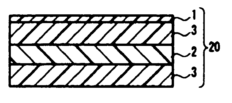
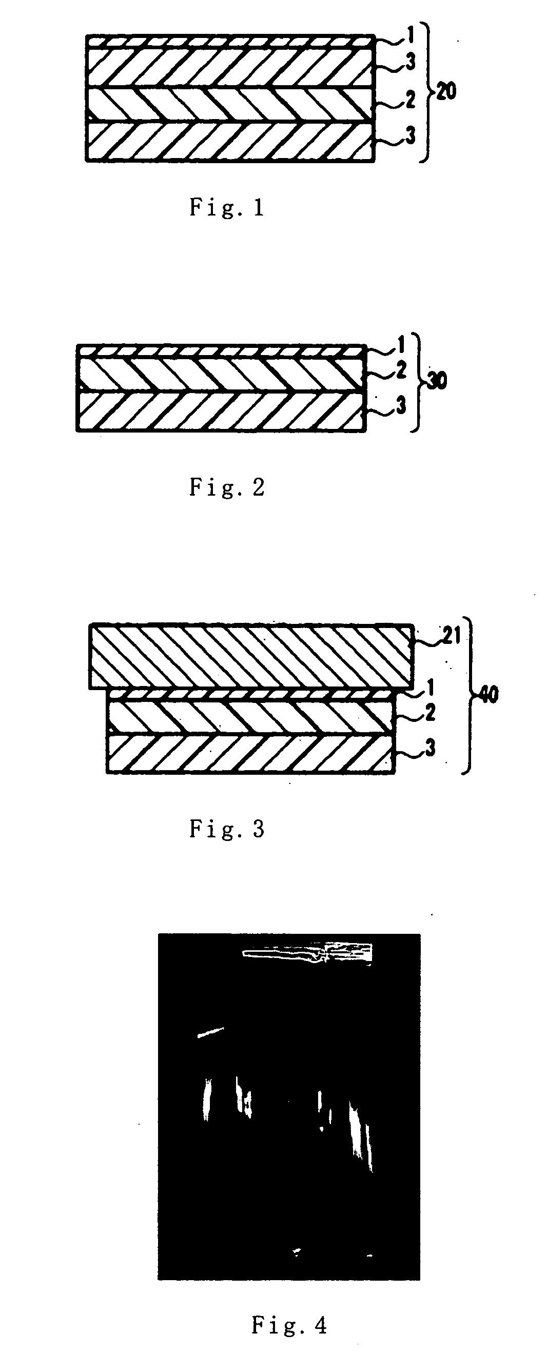
[0118] Using 2,2′-bis(3,4-dicarboxyphenyl)hexafluoropropane acid dianhydride (6FDA) and 2,2′-bis(trifluoromethyl)-4,4′-diaminobiphenyl (PFMB), polyimide (Mw=177,000) formed of the repeating unit represented by the formula (1) was synthesized. This polyimide was dissolved in MIBK, thus preparing a 14 wt % polyimide solution. After the polyimide solution was applied to a transparent film (having a thickness of about 55 μm), which will be described below, it was dried at 100° C. for 5 minutes and then dried at 150° C. for 20 minutes. In this manner, a polyimide layer (a birefringent layer) (having a thickness of 5.0 μm) was formed on the above-mentioned transparent film. The polyimide layer in the resultant optical film had a refractive index of 1.55, a birefringence (Δnxyz) in the thickness direction of 0.041 and a transmittance of 92.1%.

[0119] The above-mentioned transparent film was produced as follows. First, 65 parts by weight of a glutarimide copolymer of N-methylglutarimide and...

example 2

[0120] As described later, using 2,2′-dichloro-4,4′,5,5′-biphenyl tetracarboxylic acid dianhydride (DCBPDA) and 2,2′-bis(trifluoromethyl)-4,4′-diaminobiphenyl (PFMB), polyimide (Mw=82,500) formed of the repeating unit represented by the formula (2) below was synthesized. Except for using this polyimide, a polyimide layer (a birefringent layer) was formed on the transparent film similarly to Example 1 described above, thereby producing an optical film. The polyimide layer in the resultant optical film had a refractive index of 1.57, a birefringence (Δnxyz) in the thickness direction of 0.075 and a transmittance of 90.4%.

[0121] The above-noted DCBPDA was synthesized as follows. First, 27.2 g (0.68 mol) NaOH was dissolved in 400 ml water, and 5.0 g (0.17 mol) 3,3′,4,4′-biphenyl tetracarboxylic acid dianhydride (BPDA) was dissolved in this NaOH aqueous solution. This solution was heated up to 100° C., and a chlorine gas was injected into the solution, whereby 5 minutes after the injec...

example 3

[0124] Except for using a TAC film with a thickness of about 80 μm (trade name UZ-TAC; manufactured by Fuji Photo Film Co., Ltd.) instead of the transparent film, an optical film was produced similarly to Example 1 described above.


PUM

PropertyMeasurementUnit
transmittanceaaaaaaaaaa
thicknessaaaaaaaaaa
temperatureaaaaaaaaaa

Abstract

An optical film whose retardation distribution is uniform, whose rainbow-like irregularity is suppressed, whose color is transparent and whose optical characteristics are extremely good is provided. A birefringent material containing a non-liquid crystal polymer is dissolved in methyl isobutyl ketone so as to prepare a coating solution. This coating solution is applied onto a transparent film, thus forming a coating film. By drying the coating film, an optical film having a birefringent layer formed on the transparent film is obtained. As the non-liquid crystal polymer, it is possible to use polyimide that has a birefringence (Δnxyz) in a thickness direction when formed into a film of at least 0.03 and is soluble in methyl isobutyl ketone.

Description

TECHNICAL FIELD [0001] The present invention relates to an optical film, a liquid crystal panel and a liquid crystal display using the same. BACKGROUND ART [0002] Conventionally, in color TFT liquid crystal displays in various modes, retardation plates for optical compensation have been used widely for the purpose of achieving a higher contrast ratio over a wide viewing angle and improving color shifting. Typical retardation plates are, for example, stretched films of polycarbonate and norbornene-based polymer. However, since these stretched films have an extremely large thickness of about 25 to 100 μm and further achieve only a small retardation value in a narrow range, they have to be laminated repeatedly over each other for use as a retardation plate with sufficient characteristics. Therefore, in the case of mounting such a retardation plate on a liquid crystal display, there has been the following problem. That is, in spite of the fact that reduction in thickness and weight of l...

Claims


Application Information

Patent Timeline
Patent Type & Authority Applications(United States)
IPC IPC(8): C09K19/00G02B5/30C08G73/10C08J7/04G02F1/1335G02F1/13363
CPCG02B5/3033Y10T428/1036G02F1/13363C09K2323/03C08J5/18G02B5/30
Inventor HAYASHI, MASAKIYOSHIMI, HIROYUKI
Owner NITTO DENKO CORP
Why Eureka
Try Eureka