
Power governor for DRAM in a multi-node computer system
a multi-node computer system and power governor technology, applied in the direction of power supply for data processing, liquid/fluent solid measurement, instruments, etc., can solve the problems of putting the power supply to its capacity limit, not having the complete awareness of the power usage of the entire system, significant challenge to today's system design, etc., to achieve the maximum accuracy, efficiency and performance of the memory subsystem
- Summary
- Abstract
- Description
- Claims
- Application Information
AI Technical Summary
Benefits of technology
Problems solved by technology
Method used
Image

Examples
Embodiment Construction
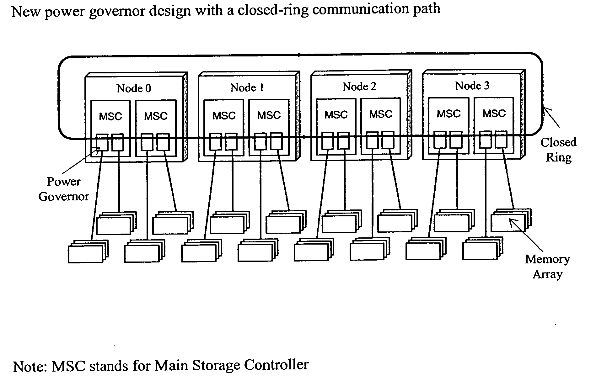
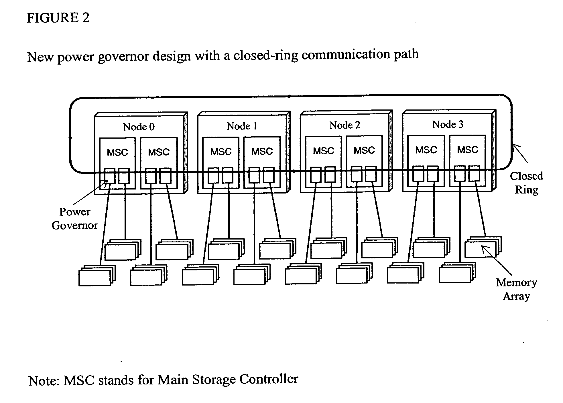
[0019] As shown in our preferred embodiment of FIG. 2, in order to make all the power governors work together cohesively, we established a closed-ring communication path that runs across all the power governors in the system. As shown in FIG. 2 we have provided a plurality of nodes (0, 1, 2, 3) arranged in a ring, each having a plurality of memory system controller MSC interfaces to a DRAM memory array. Since it is a closed ring, each of the power governors has its predecessor and successor. There is a power usage number that circulates in this ring. The number represents the total measurement of memory commands that has been utilized so far within the system. The time interval that the number circulates through the ring once is defined as the number circulation period.
[0020] While the power usage number is circulating in the ring, each governor keeps counting on its local activities. Whenever the usage number arrives at a power governor, the governor adds its local measurement on ...
PUM
 Abstract
Description
Claims
Application Information