Macroscopic assembly of nanometric filamentary structures and method of preparation thereof

a nano-scale, filamentary technology, applied in the field of nano-scale filamentary structures, can solve the problems of difficult deposit or recovery, inability to optimize, and relatively difficult to recover, so as to achieve the effect of efficient separation of different samples, avoiding the maintenance of quality, size, and other properties as constants

Inactive Publication Date: 2006-09-28
INST NAT DE LA FLECHERCHE SCI
View PDF13 Cites 29 Cited by
  • Summary
  • Abstract
  • Description
  • Claims
  • Application Information

AI Technical Summary

Benefits of technology

[0037] According to another aspect of the invention, there is provided a continuous method for depositing nanometric filamentary structures on electrodes. The method comprises passing a gaseous phase comprising the nanometric filamentary structures between at least two electrodes of a selected a set of electrodes (i.e. first set) generating an electric field for depositing the nanometric filamentary structures on at least one of the electrodes of the set; and then, at a desired time, selecting another set of electrodes (i.e. second set) comprising at least two electrodes and passing therebetween the gaseous phase for depositing the nanometric filamentary structures on at least one of the electrodes of the other set. The method preferably comprises the step of recovering the deposited structures from the set of electrodes while depositing structures between the other set of electrodes. The person skilled in the art would understand that such a method can be performed if there are at least two sets of electr

Problems solved by technology

Since many of these nanometric filamentary structures can be particularly volatile, they are difficult to deposit or recover without loosing at least a portion of them.
Such a technique is not optimized for a large-scale production and often results in a deposit having a powder or membrane form that is relatively difficult to recover.
A difficulty encountered with the synthesis of single-wall carbon nanotubes, especially for their recovery, is that they are very volatile and they can be lost during the synthesis.
In the methods and apparatuses that have been proposed so far for producing nanometric filamentary structures, there is no proposed solution that is efficient in order to determine the quality and/or quantity of the produced structures during the synthesis, In fact, such an analysis is made only when the production is stoppe

Method used


Image

  • Macroscopic assembly of nanometric filamentary structures and method of preparation thereof
  • Macroscopic assembly of nanometric filamentary structures and method of preparation thereof
  • Macroscopic assembly of nanometric filamentary structures and method of preparation thereof

Examples


example 1

Deposition of Nanometric Filamentary Structures

[0194] An experiment was carried out by using an apparatus for depositing nanometric filamentary structures according to a preferred embodiment of the invention. For this experiment an apparatus similar to the apparatus schematically represented in FIG. 4 was used. The apparatus for depositing filamentary structures was used downstream of a plasma torch for producing single-wall carbon nanotubes for depositing such structures. The plasma torch used was similar to the plasma torch represented in FIG. 1 of US 2003 / 0211030, which is hereby incorporated herein by reference in its entirety. All the parameters related to the plasma torch are controlled by a computer using the LABVIEW® software. The parameters can also be manually controlled. The inert gas used for generating the primary plasma was argon, the metal catalyst was ferrocene, the carbon-containing gas was ethylene and the cooling gas was helium. Helium was also injected toward th...

example 2

Deposition of Nanometric Filamentary Structures

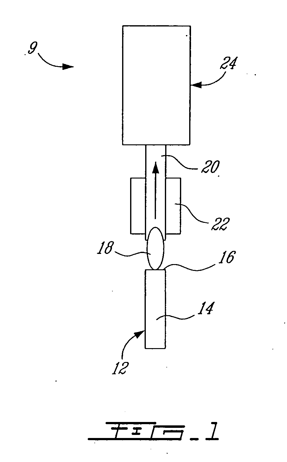
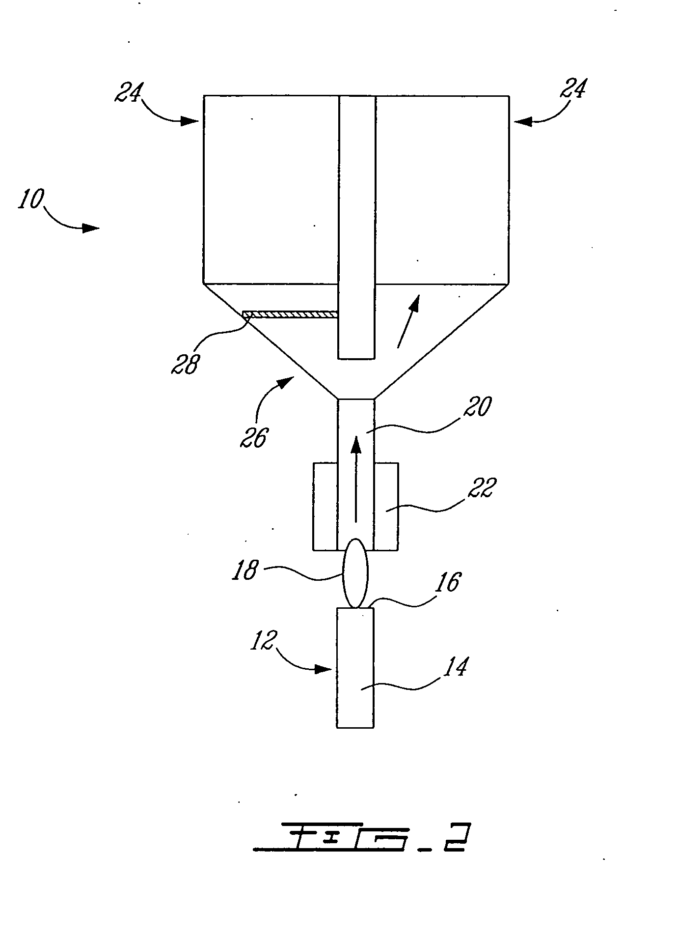
[0196] This example was carried out using an apparatus for depositing nanometric filamentary structures similar to the apparatus shown in FIG. 12. More particularly, the apparatus for depositing the nanometric filamentary structures was disposed downstream of a plasma torch for producing single-wall carbon nanotubes (as shown in FIG. 1). The plasma torch used was similar to the plasma torch described in FIG. 2 of US 2003 / 0211030. The plasma torch was operated in a similar manner as described for Example 1.

[0197] As the production of single-wall carbon nanotubes begins in the plasma torch process, the gaseous phase containing the particles synthesized or the nanometric filamentary structures are supplied to the inlet of the deposition apparatus. This gaseous phase is similar to a smoke and is accumulating in the deposition chamber, where a voltage is applied on the central electrode in order to generate a electric field. In the present...

example 3

Monitoring the Production of Nanometric Filamentary Structures

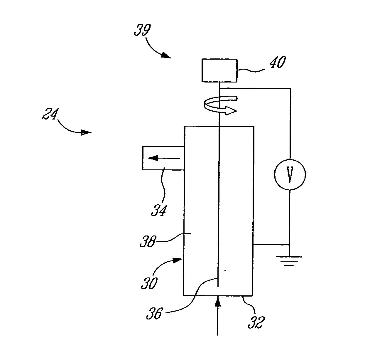
[0201] This example was carried out using an apparatus similar to the apparatus shown in FIG. 13. More particularly, the apparatus for monitoring the production of nanometric filamentary structures was mounted on an apparatus for depositing nanometric filamentary structures similar to the apparatus shown in FIG. 12. The apparatus for depositing nanometric filamentary structures was disposed downstream of a plasma torch for producing single-wall carbon nanotubes as shown in FIG. 1 and as described in Example 2. In the present example, the particular behavior of the suspended carbon nanotubes in a gaseous phase, when submitted to an electric field, was used in order to detect and monitor the production of nanotubes.

[0202] The optimal conditions for the synthesis of single-wall carbon nanotubes are varying when modifications are done in the plasma used in the synthesis process. For example, if the cooling parameters of the...


PUM

PropertyMeasurementUnit
Lengthaaaaaaaaaa
Lengthaaaaaaaaaa
Lengthaaaaaaaaaa

Abstract

The invention relates to a macroscopic assembly of nanometric filamentary structures. The macroscopic assembly comprises a plurality of microscopic assemblies substantially aligned in a same direction and connected together. Each of the microscopic assemblies comprises a plurality of members defining a plurality of spaces therebetween. Each of the members comprises a nanometric filamentary structure or a bundle of nanometric filamentary structures, wherein the macroscopic assembly has a density of less than 8 mg/cm3. The is also provided a method for prerparing such a macroscopic assembly.

Description

CROSS-REFERENCE TO RELATED APPLICATION [0001] The present application claims priority on U.S. provisional application No. 60 / 664,953 filed on Mar. 25, 2005, which is incorporated herein by reference in its entirety.FIELD OF THE INVENTION [0002] The present invention relates to improvements in the field of nanometric filamentary structures. More particularly, the invention relates to macroscopic assemblies of nanometric filamentary structures such as single-wall carbon nanotubes or multi-wall carbon nanotubes. It also relates to methods and apparatuses for preparing such macroscopic assemblies. The invention further relates to methods and apparatuses for depositing nanometric filamentary structures as well as others methods and apparatuses that can be useful in the production of nanometric filamentary structures. BACKGROUND OF THE INVENTION [0003] In the last decade, several nanometric filamentary structures have been synthesized. In fact, the interest for these one-dimensional struc...

Claims


Application Information

Patent Timeline
IPC IPC(8): H01M4/58C01B31/02D01F9/127B01J19/08
CPCB82Y30/00Y10T428/30C01B31/0233C01B2202/02C01B2202/34D01D7/00D01F9/127D01F9/133D04H3/02D04H3/16H01M4/8605H01M4/96Y02E60/50Y10S977/742B82Y40/00C01B32/162B82B1/00B82Y25/00
Inventor LAROUCHE, FREDERICSMILJANIC, OLIVIERSTANSFIELD, BARRY L.
Owner INST NAT DE LA FLECHERCHE SCI
Why Eureka
Try Eureka