
Diesel emissions control system and method

Inactive Publication Date: 2006-10-05
WILLIAM J BRADY LOVING TRUST THE
View PDF12 Cites 19 Cited by
  • Summary
  • Abstract
  • Description
  • Claims
  • Application Information

AI Technical Summary

Benefits of technology

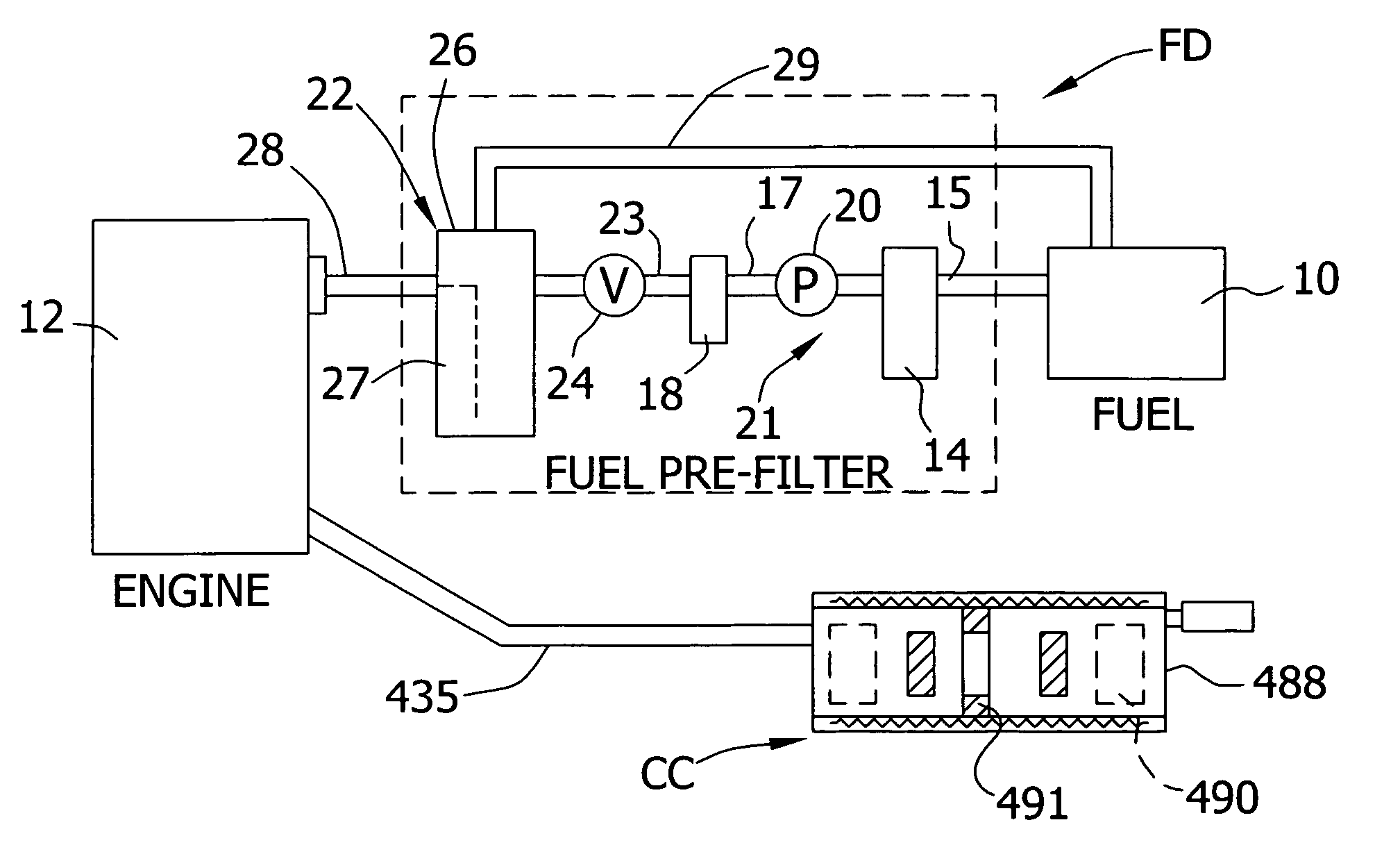
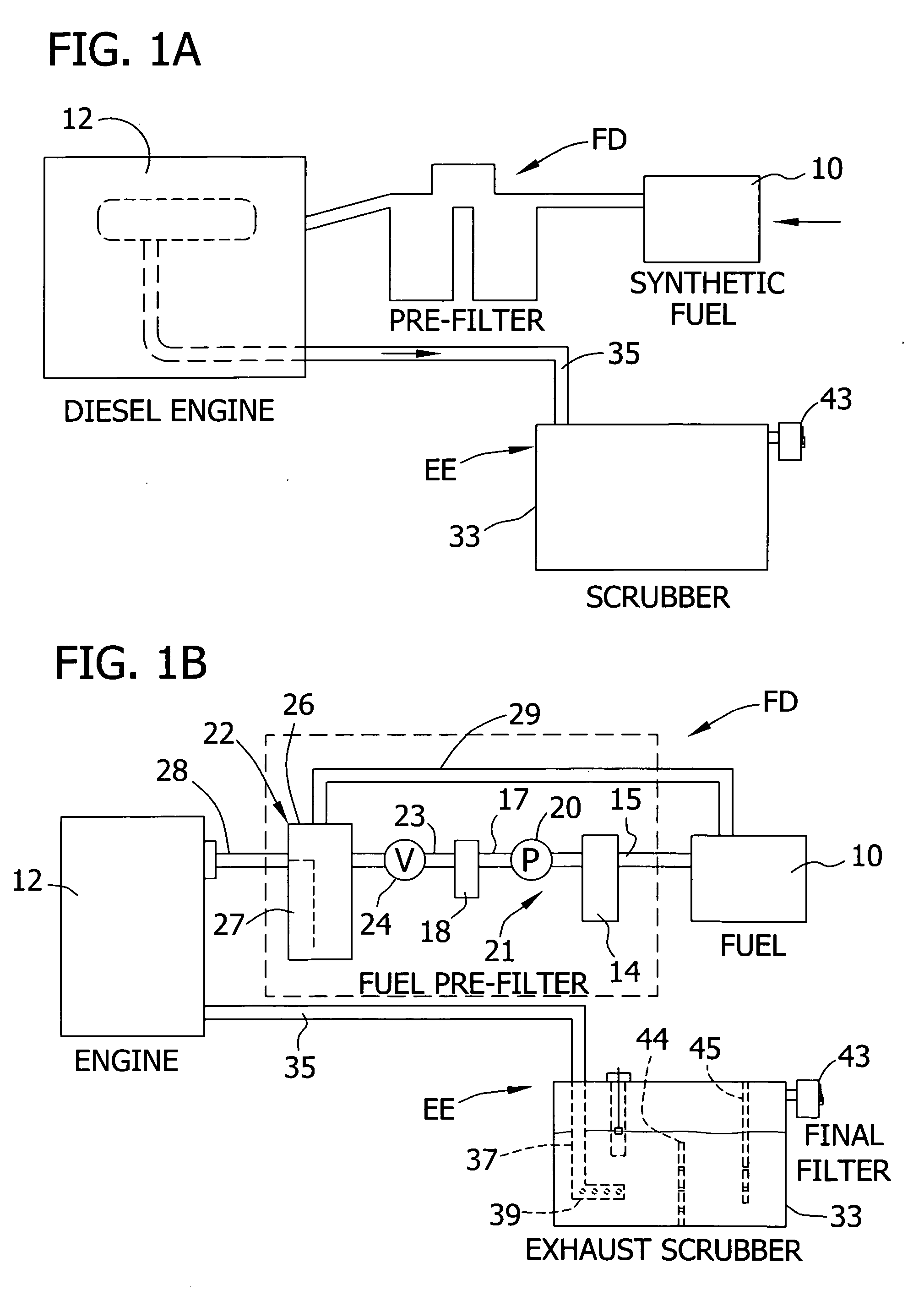
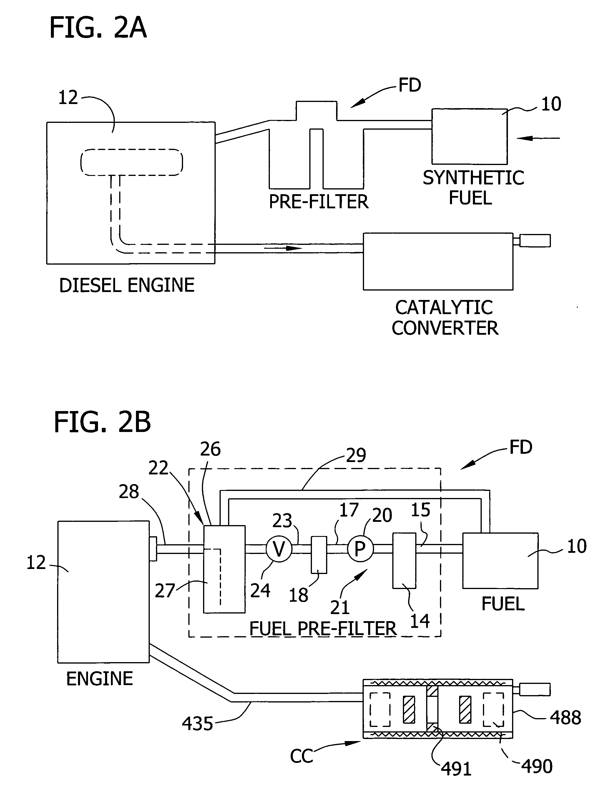
[0011] The invention is embodied in systems for reducing diesel particulate matter (DPM) in diesel engine emissions by providing a high paraffinic diesel fuel having a Cetane rating greater than 60 and substantially no sulfur, aromatics or nitrogen content, and using such fuel alone or in combination with filtration means comprising an aqueous filter apparatus forming a water bath having a major water portion and a minor portion of super-wetting agent with a high affinity for hydrocarbons. The invention is further embodied in a diesel emissions control methods including the features of high paraffinic diesel fuel selection, pre-filtering diesel fuel, and removing DPM from diesel emissions through an aqueous solution having a minor portion of a low foam super-wetting agent.

Problems solved by technology

Internal combustion engines are designed to operate most efficiently on standard quality fuels, and the presence of impurities or non-combustible contaminates may result in poor engine performance or impairment as well as produce higher levels of exhaust impurities.
Even small quantities of water in diesel fuel may prevent satisfactory operation of a diesel engine, and most diesel engines now have some type of water-separator in addition to filters for removing sediment or other solids that may have been introduced into the fuel tank.
It is also now known that the presence of air entrained in diesel fuel delivered to a fuel injection system results in poorer engine performance since the amount of air required for optimum combustion is already precisely controlled by the fuel injection system itself.
In addition, the sulfur content in petroleum-based diesel fuels, including No. 2 diesel products, is one of the major reasons the fuel injectors catalytic converters fail.
It is thus clear that the presence of these non-fuel contaminates in a diesel fuel delivery system result in poor engine performance with the extended result of less complete fuel burning and an increase in deleterious exhaust pollutants.
The control of exhaust gas emissions has been a primary troublesome concern for health and safety reasons, and the Federal government has heretofore mandated the use of “soot trap filters” to reduce DPM emissions levels by filtering hydrocarbons out of the diesel exhaust gases.
However, the use of dry filter soot traps on the end of a diesel exhaust has generally posed a fire hazard problem irrespective of what the filter material (steel, fibreglass, ceramic, etc.) is made of, since any buildup of DPM hydrocarbons at normal engine and exhaust operating temperatures may cause an explosion in a gaseous coal mine.
High exhaust gas temperatures are especially hazardous in the operation of class 32 diesel engines in coal mines or like closed environments where methane gas may be present.
The result is that many mine operators refuse to use the mandated soot traps for safety reasons and generally continue to operate under violation citations from the Mine Safety and Health Administration (MSHA), which has promulgated a low—and heretofore unachievable-DPM emissions level of 2.5 gr / bhp-hr.
It has been reported that dry soot traps are still fire hazards even after the engine is shut off because oxygen will flow from ambient back into the hot trap and ignite the carbon / hydrocarbon DPM accumulation therein.
In short, any dry soot trap per se almost always poses a fire hazard and, in addition, soot traps are labor intensive and expensive.
However, the apparatus of these patents primarily only cools the exhaust gas, but has no other major effect since only a small portion of DPM matter will be trapped in plain hard mine water, and also no significant carbon monoxide or sulfur will be removed.
Diesel equipment in such closed operations may be subject to regulation by the MSHA because of the environmental health hazards caused by particulate matter (PM) emissions therein.

Method used


Image

  • Diesel emissions control system and method
  • Diesel emissions control system and method
  • Diesel emissions control system and method

Examples


Embodiment Construction

[0032] Emission control systems of the prior invention will be more clearly understood with reference to the following definitions. DEFINITIONS:

[0033]“Synthetic Fuel” is used herein as a generic term identifying a class of diesel engine fuels that encompasses synthetic fuel blends and specified solvent fuels. Synthetic fuels are produced by processes, such as Fischer-Tropsch (F-T), for converting gas-to-liquid (GTL) or coal-to-liquid (CTL). The synthetic fuels of this invention are further characterized by a high Cetane number, and low sulfur(S), aromatics (A) and nitrogen (N) constituents resulting in a clean burning fuel having low PM emissions.

[0034]“Synthetic fuel blends” is used to identify a form of synthetic diesel fuel having a preponderance of synthesized components combined with a minor portion of a petroleum-derived constituent.

[0035]“Solvent fuels” is used herein to identify a group of products synthesized by F-T processes or the like and having the characteristics of...


PUM

PropertyMeasurementUnit
Fractionaaaaaaaaaa
Fractionaaaaaaaaaa
Fractionaaaaaaaaaa

Abstract

The invention is embodied in a diesel system for reducing particulate matter emissions in off-road vehicles, coal mining and metal / non-metal mining operations, comprising, in combination, a supply of highly paraffinic diesel fuel having a high Cetane rating and substantially no sulfur, aromatics and nitrogen content and being formulated to greatly reduce PM output levels from the engine relative to conventional diesel fuels, The invention is further embodied in the method of reducing diesel emission contaminants including providing a supply of highly paraffinic diesel fuel having a negligible sulfur, aromatics or nitrogen content, and a high Cetane number, and other apparatus useful for filtering engine emissions before discharge to ambient.

Description

CROSS-REFERENCE TO RELATED APPLICATIONS [0001] This is a continuation-in-part of U.S. application Ser. No. 11 / 194,371 filed Aug. 1, 2005 which was a continuation-in-part of application Ser. No. 11 / 074,595 filed Mar. 8, 2005, the entire disclosures of both earlier applications being incorporated herein by reference.BACKGROUND OF THE INVENTION [0002] 1. Field of the Invention [0003] This invention relates generally to diesel fuel systems, and more particularly to diesel systems and methods for substantially reducing hydrocarbon and diesel particulate matter levels in diesel exhaust emissions to safe environmental levels particularly in underground mining. [0004] 2. Description of the Prior Art [0005] Internal combustion engines are designed to operate most efficiently on standard quality fuels, and the presence of impurities or non-combustible contaminates may result in poor engine performance or impairment as well as produce higher levels of exhaust impurities. Even small quantities ...

Claims


Application Information

Patent Timeline
IPC IPC(8): F01N3/00F02M37/24F02M37/54
CPCB01D53/92F01N13/009F01N1/083F01N1/10F01N3/033F01N3/04F01N3/043F01N3/20F01N2230/04F01N2330/06F01N2330/10F02B3/06F02M37/221Y02T10/20B01D47/021B01D47/022C10L1/08F02M37/24F02M37/54Y02A50/20Y02T10/12
Inventor BRADY, WILLIAM J.
Owner WILLIAM J BRADY LOVING TRUST THE
Learn More