Fabrics with multi-segment, paired, interchanging yarns
- Summary
- Abstract
- Description
- Claims
- Application Information
AI Technical Summary
Benefits of technology
Problems solved by technology
Method used
Image

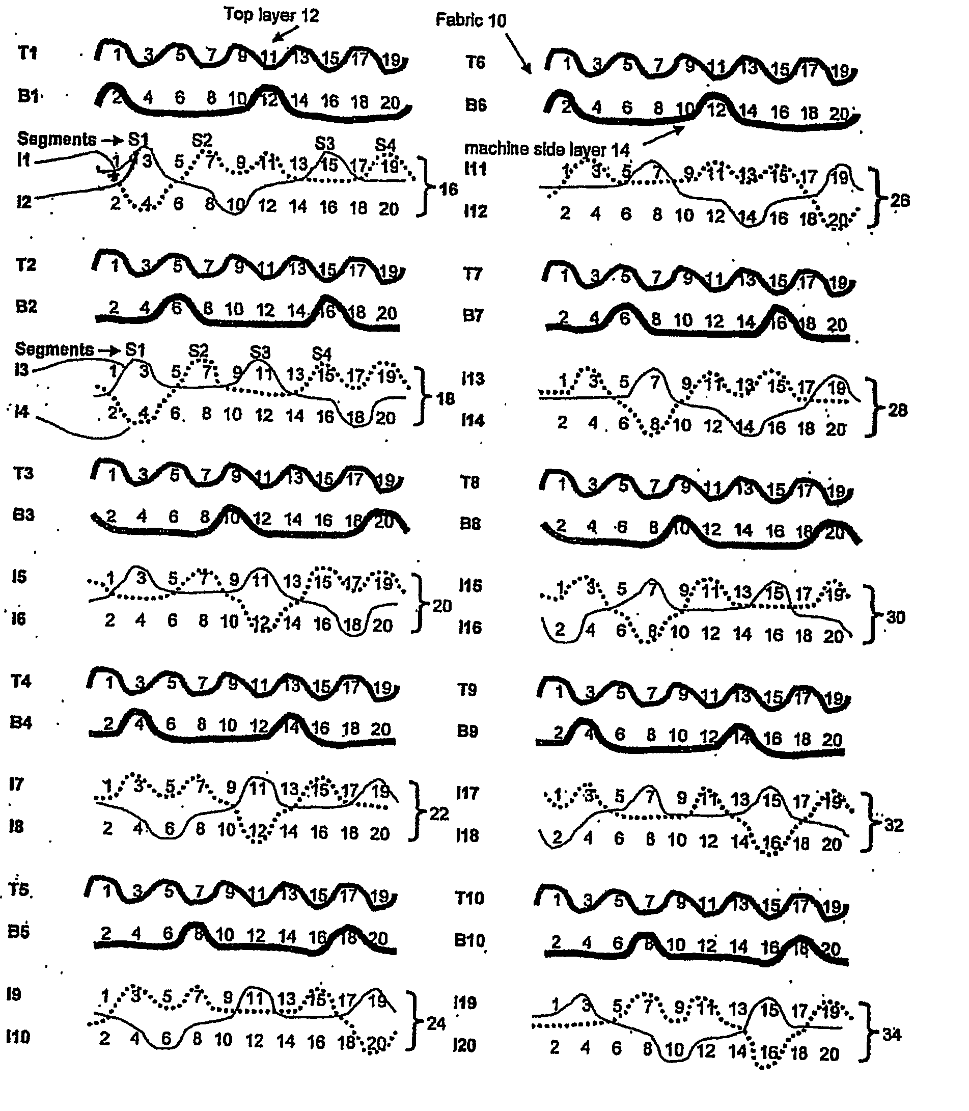
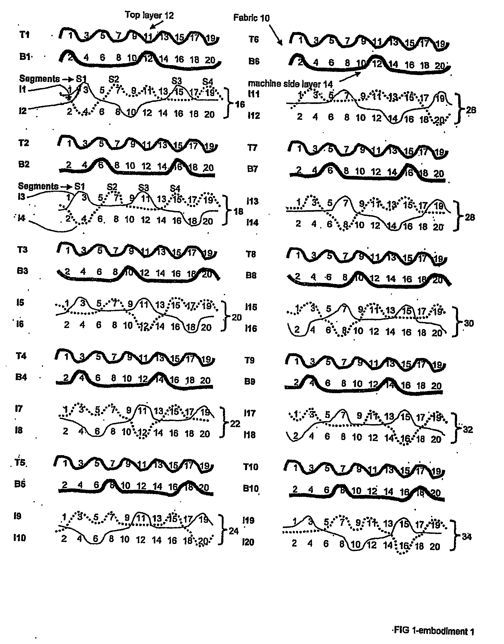
Examples
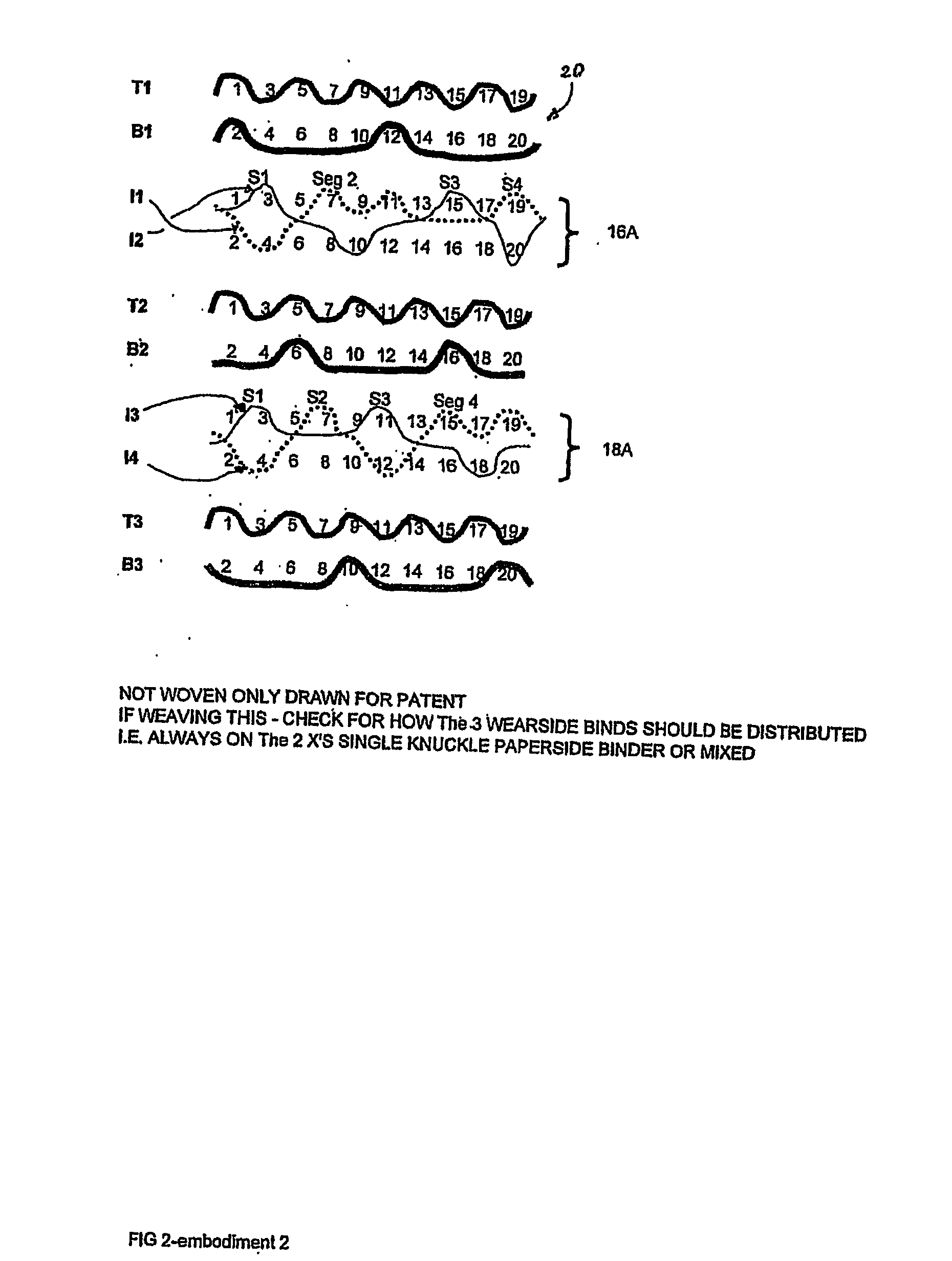
second embodiment
[0073] Referring now to FIG. 2, the weave paths for a number of paperside wefts, wearside wefts and pairs of intrinsic interchanging weft binder yarns are Illustrated for a fabric 20 in accordance with this invention. The fabric 20 is a 20 shaft fabric and is the same as the fabric 10, with one exception. In the fabric 20 one of the intrinsic interchanging weft binder yarns in each pair of intrinsic interchanging weft binder yarns binds with an additional wearside warp yarn such that regions under three segments are bound by a binder yarn. In intrinsic interchanging weft binder yarn pair 16A binder I1 binds with one single machine side warp yarn (4) within each repeat, and the binder I2 binds with two single machine side warp yarns (10 and 20, respectively) within each repeat. The machine side warp yarns 4, 10, 20 bound by interchanging weft binder yarns I1, I2 are adjacent each other, i.e., underlying segment 1 and adjacent segments 2 and 4 in the weave repeat, respectively.
third embodiment
[0074] Referring to FIG. 3, the weave paths for a number of weft yarns in a fabric in accordance with this invention is illustrated, and the fabric employing this weave construction is identified as 30. The fabric 30 is identical to the fabric 10, with one exception. The fabric 30 includes intrinsic interchanging weft binder pairs 16B, 18B, etc. The fabric 30, like the fabric 10, has a 2:1 effective ratio of paperside to wearside weft paths. However, in comparison to the fabric 10, the fabric 30 has pairs of intrinsic binder yarns replaced by single paper side weft yarns such that the binder pairs no longer alternate with all of the top weft yarns T1, T2, etc. As illustrated single paper side weft yarn T3 replaces an interchanging binder yarn pair of the type employed in the fabric 10. This provides a means to further adjust the properties of the fabrics in accordance with this invention. This technique may be utilized for all embodiments of the invention such that there may be one,...
fifth embodiment
[0081] Referring to FIG. 5, this invention is fully illustrated at 50, which is a fabric having a 28 shaft repeat. An intrinsic interchanging weft binder pair employed in the fabric 50 in accordance with this invention is illustrated at 16D. All of the intrinsic interchanging weft binder yarn pairs employed in this embodiment can be of the same structure as pair 16D, and actually are all illustrated in FIG. 5.
[0082] In the fabric 50 illustrated in FIG. 5, the 14 paper side wefts T1,T2,T3 . . . T14 interlace with the 14 paper side warps 1,3,5 . . . 27 within each weave repeat in an “over one-under one sequence,” such that each weft makes 7 repeats of plain weave within the 14 paper side warp weave repeat. The 14 wear side wefts B1, B2 . . . B14 interlace with the 14 wear side warps 2,4,6 . . . 28 within each weave repeat in seven shaft repeat in which each wear side weft follows an “over one-under 6 sequence” to make 2 repeats of 7 shaft within each full weave repeat. The 14 intercha...
PUM
 Abstract
Description
Claims
Application Information
 - R&D
- Intellectual Property
- Life Sciences
- Materials
- Tech Scout
- Unparalleled Data Quality
- Higher Quality Content
- 60% Fewer Hallucinations
Browse by: Latest US Patents, China's latest patents, Technical Efficacy Thesaurus, Application Domain, Technology Topic, Popular Technical Reports.
© 2025 PatSnap. All rights reserved.Legal|Privacy policy|Modern Slavery Act Transparency Statement|Sitemap|About US| Contact US: help@patsnap.com