Discrete track media and method of manufacturing the same

a technology manufacturing method, which is applied in the field of discrete track media, can solve the problems of difficult to allow the magnetic head to fly stably over the media surface, interfere with adjacent tracks, and achieve the effect of reducing the distance between recording tracks

Inactive Publication Date: 2006-10-05
KK TOSHIBA
View PDF0 Cites 70 Cited by
  • Summary
  • Abstract
  • Description
  • Claims
  • Application Information

AI Technical Summary

Benefits of technology

[0012] A method of manufacturing a discrete track media according to another aspect of the present invention comprises: forming a ferromagnetic layer and a protective layer on a nonmagnetic substrate; applying a resist to the protective layer; imprinting a stamper, having patterns of protrusions and recesses corresponding to a recording track, a preamble zone, an address zone and a burst zone, onto the resist so as to transfer the patterns to the resist; carrying out dry-etching to selectively remove bottoms of the recesses in the resist to which the patterns of the protrusions and recesses have been transferred; ion-beam etching the protective layer and the ferromagnetic layer using the patterned resist as a mask; carrying out sputtering to fill a nonmagnetic material into the recesses between patterns of the ferromagnetic layer with the patterned resist remained on the protective layer; and performing etchback to reduce a thickness of the nonmagnetic material.

Problems solved by technology

In recent years, the improved track density of hard disk drives (HDD) has disadvantageously resulted in the interference between adjacent tracks.
It is difficult to allow the magnetic head to fly stably over the media surface with protrusions and recesses.
However, the DTR media is only effective in reducing the distance between the recording tracks and can only improve the density in the cross-track direction.
Since a magnetic field generated by a magnetic head is limited, however, it is very difficult to record data to the high-coercivity media in the perpendicular recording system.
This degrades the reliability of the magnetic recording device (HDD).
When the magnetic head comes into contact with the media during an operation of reading servo signals, particularly burst signals, necessary to control the position of the magnetic head, tracking cannot be achieved, which prevents the HDD from functioning.

Method used


Image

  • Discrete track media and method of manufacturing the same
  • Discrete track media and method of manufacturing the same
  • Discrete track media and method of manufacturing the same

Examples


example 1

[0095] A disk stamper with 100 sectors of recording tracks and servo regions was formed by electron-beam exposure. The stamper was designed so that the area ratio of the ferromagnetic layer to the nonmagnetic material was 3 to 1 in the data region and 4 to 1 in the burst zone. The stamper was used to produce a discrete track media according to the method shown in FIGS. 6A to 6H, as described below.

[0096] A soft magnetic layer of CoZrNb was formed on a glass substrate to a thickness of about 200 nm. A Ru underlayer for orientation control was deposited to a thickness of about 20 nm by sputtering. A ferromagnetic layer formed of CoCrPt alloy added with SiO2 was then deposited to a thickness of about 20 nm. To prevent natural oxidation, a carbon protective film was deposited on the surface of the ferromagnetic layer to a thickness of about 4 nm. The media was determined to have a coercivity of 5 kOe on the basis of a Kerr hysteresis loop. A resist of SOG was formed so as to have a thi...

example 2

[0101] The experiment described below was conducted in order to examine the magnetic head for vibration that may occur if there is a large difference b in the height of the nonmagnetic material between the burst zone and the data region.

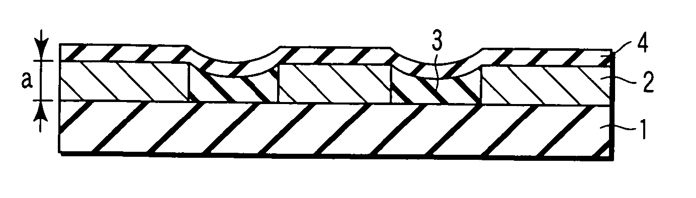
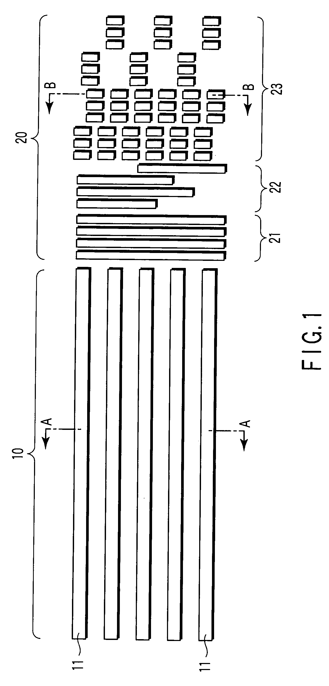
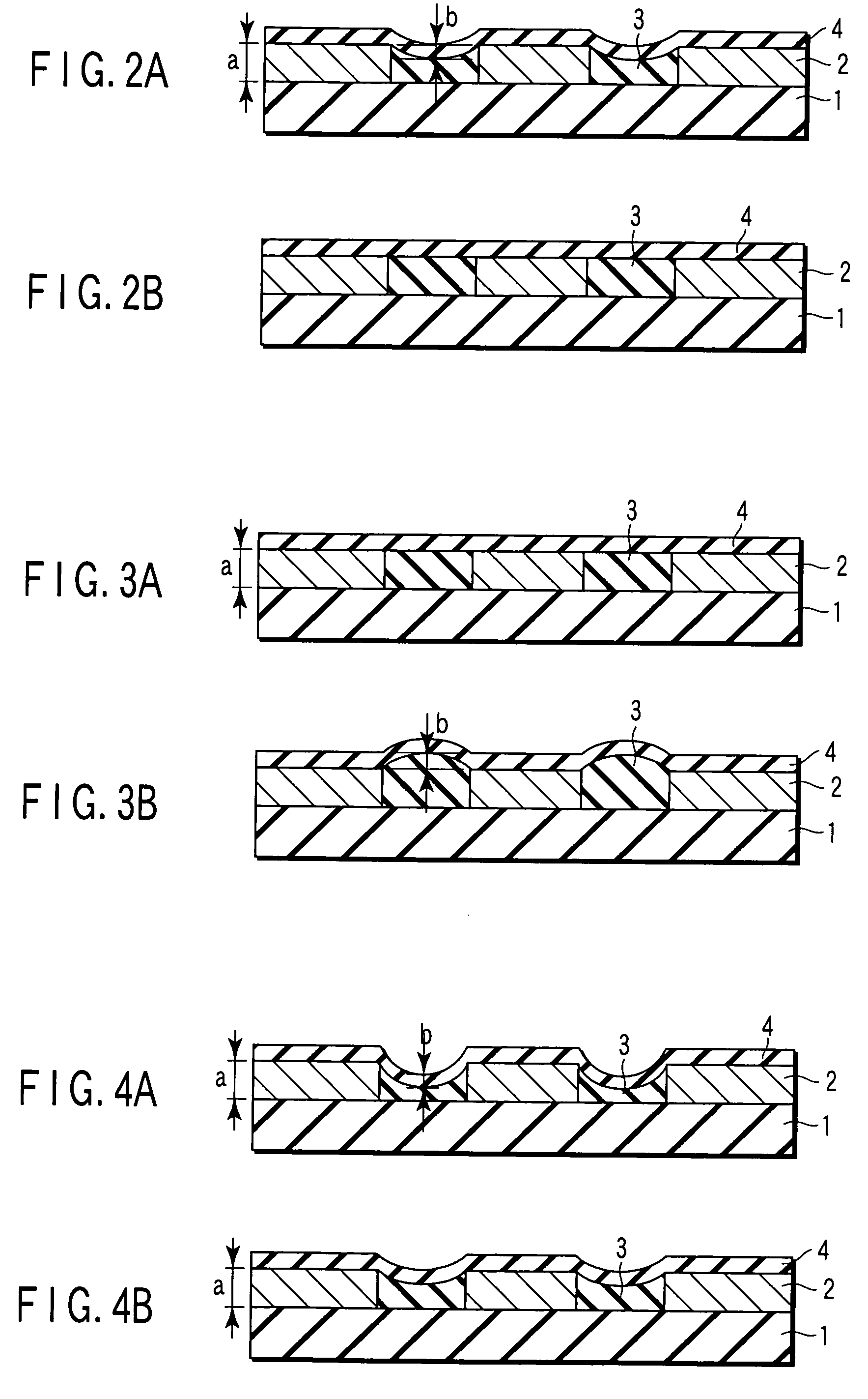
[0102] As shown in FIG. 9, a DTR media was manufactured in which no servo patterns were formed, while only the data regions are processed. As shown in FIG. 10A, protrusions and recesses are present in the data region. However, as shown in FIG. 10B, the burst zone is formed into a mirror state. A milling time was varied to produce three types of DTR media in which the protrusions had a height of 20, 15, or 10 nm in the data region. The height of the protrusions corresponds to the difference b in the height of the nonmagnetic material between the burst zone and the data region. A laser Doppler vibrometer (LDV) was used to observe the head flying. For the DTR media with 20 nm of b value, vibration of 9 kHz was observed which corresponded to a frequency...

example 3

[0103] Besides SiO2, Au, Ag, Cu, C, CN, Si3N4, BN, TiN, SION, SiC, BC, TiC, or Al2O3 was used as a nonmagnetic filling agent. A DTR media was produced in a manner similar to that used in Example 1 except for this condition.

[0104] When Au, Ag, or Cu was used as the filling agent, both the data region and burst zones had a flat filled structure owing to reflow. When C, CN, Si3N4, BN, TiN, SiON, SiC, BC, TiC, or Al2O3 was used as the filling agent, sectional TEM observation showed that the DTR media produced had the structure shown in FIGS. 2A and 2B. However, in these DTR media, the film was stripped off the disk surface in places. Here, when C was used as the filling agent, the film strip-off occurred only in a relatively small number of places. These results are probably due to the difference in adhesion between the patterned resist (SOG) and the filling agent. That is, SOG and SiO2 are substantially the same material and adhere excellently to each other. However, the other materia...


PUM

PropertyMeasurementUnit
heightaaaaaaaaaa
thicknessaaaaaaaaaa
coercivityaaaaaaaaaa

Abstract

A discrete track media has a nonmagnetic substrate, and a magnetic recording layer provided on the nonmagnetic substrate and having a data region including a recording track and a servo region including a preamble zone, an address zone and a burst zone, the data region and the servo region include patterns of a ferromagnetic layer forming protrusions and a nonmagnetic material filled into recesses between the patterns of the ferromagnetic layer, in which a height of the nonmagnetic material filled into the recesses in the data region is lower than that in the burst zone.

Description

CROSS-REFERENCE TO RELATED APPLICATIONS [0001] This application is based upon and claims the benefit of priority from prior Japanese Patent Application No. 2005-097971, filed Mar. 30, 2005, the entire contents of which are incorporated herein by reference. BACKGROUND OF THE INVENTION [0002] 1. Field of the Invention [0003] The present invention relates to a discrete track media which allows a magnetic head to fly appropriately and to which high-density magnetic recording can be carried out, as well as a method of manufacturing the discrete track media. [0004] 2. Description of the Related Art [0005] In recent years, the improved track density of hard disk drives (HDD) has disadvantageously resulted in the interference between adjacent tracks. In particular, to reduce the fringing effect of magnetic fields from a magnetic head has become an important technical object. [0006] To solve this problem, it is expected that a discrete track recording media (a DTR media) having physically se...

Claims


Application Information

Patent Timeline
Patent Type & Authority Applications(United States)
IPC IPC(8): G11B5/64
CPCB82Y10/00G11B5/59655G11B5/865G11B5/82G11B5/855G11B5/743
Inventor KAMATA, YOSHIYUKISAKURAI, MASATOSHISUGIMURA, SHINOBUSHIROTORI, SATOSHI
Owner KK TOSHIBA
Why Eureka
Try Eureka