Electric motor driven traversing balancer hoist

a technology of electric motors and balancers, which is applied in the direction of hoisting equipment, transportation and packaging, instruments, etc., can solve the problems of complicated control of servo motors, affecting the performance of trolley drive systems, and causing a lot of damage to the system, so as to prevent any possible system effects and improve the performance of the trolley drive system

Active Publication Date: 2006-10-12
ZAGUROLI JR JAMES
View PDF30 Cites 40 Cited by
  • Summary
  • Abstract
  • Description
  • Claims
  • Application Information

AI Technical Summary

Benefits of technology

[0024] The #2 load sensor is used when the hoist control system is switched to a manual control as by activation of a push button switch on the control box. A handle grip is mounted to be slidable on the lower load shaft and connected via the #2 load sensor to the upper load shaft. The #2 load sensor creates signals in response to up or down pressure exerted on the control grip by the user causing up or down hoist operation in correspondence to up or down force applied to the grip. Forces applied to the grip do not affect the #1 load sensor since the #1 load sensor is connected bel

Problems solved by technology

If the cable breaks, a hazard can be created by whipping of the cable caused by release of the stored energy when the cable breaks or when there is some other failure.
The control of the servo motor is made more complicated by the cable stretch and the momentum of the rotating components, creating complex dynamics, particularly at the high speeds which the electric servo motor drive systems operate.
However, the mass of a chain wound on a drum is relatively great, and when combined with the mass of a planetary gear set, this affects the response of an electric motor driven balancer hoist.
The weight of an operator's hand can upset the “float” bala

Method used


Image

  • Electric motor driven traversing balancer hoist
  • Electric motor driven traversing balancer hoist
  • Electric motor driven traversing balancer hoist

Examples


Embodiment Construction

[0046] In the following detailed description, certain specific terminology will be employed for the sake of clarity and a particular embodiment described in accordance with the requirements of 35 USC 112, but it is to be understood that the same is not intended to be limiting and should not be so construed inasmuch as the invention is capable of taking many forms and variations within the scope of the appended claims.

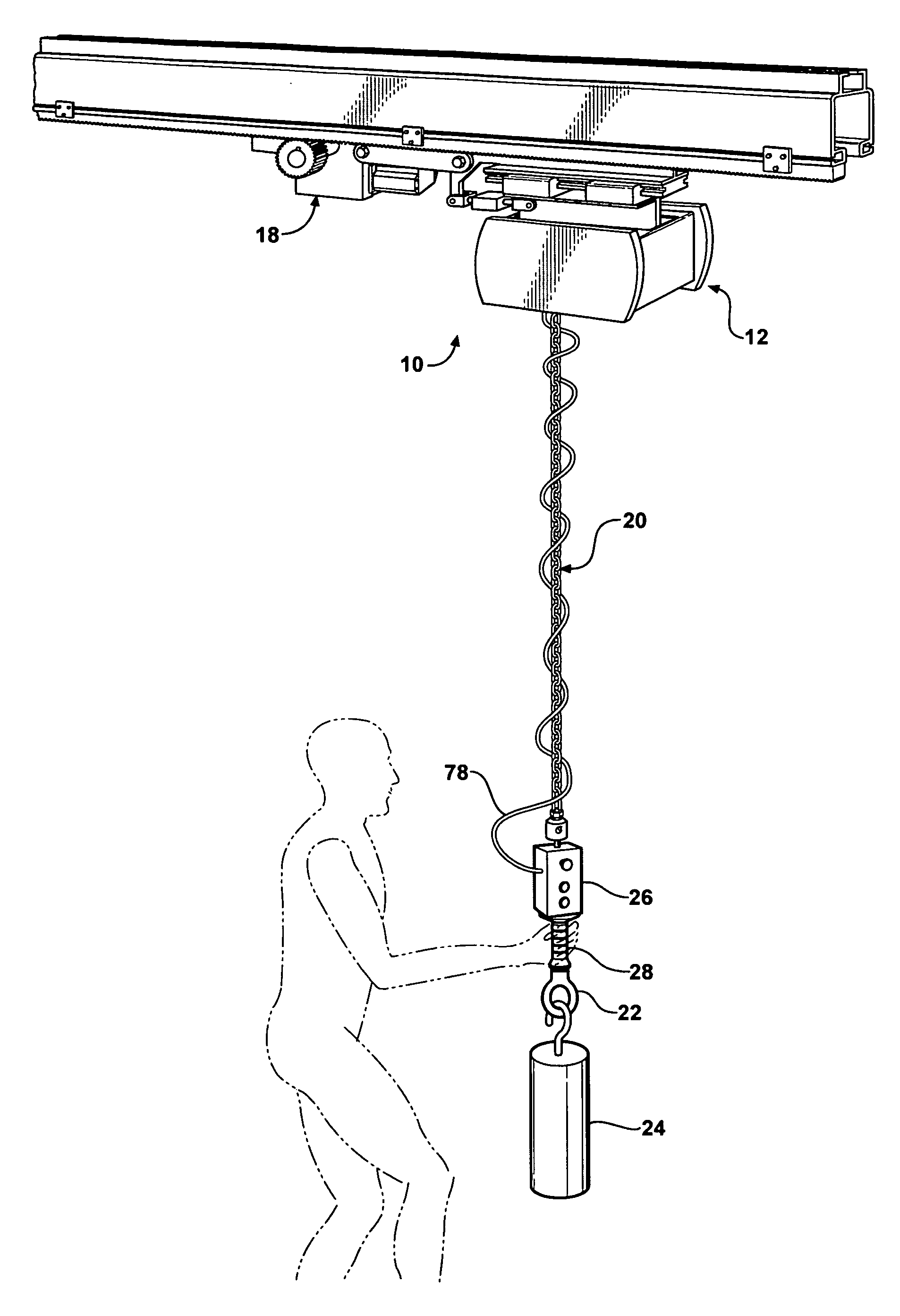
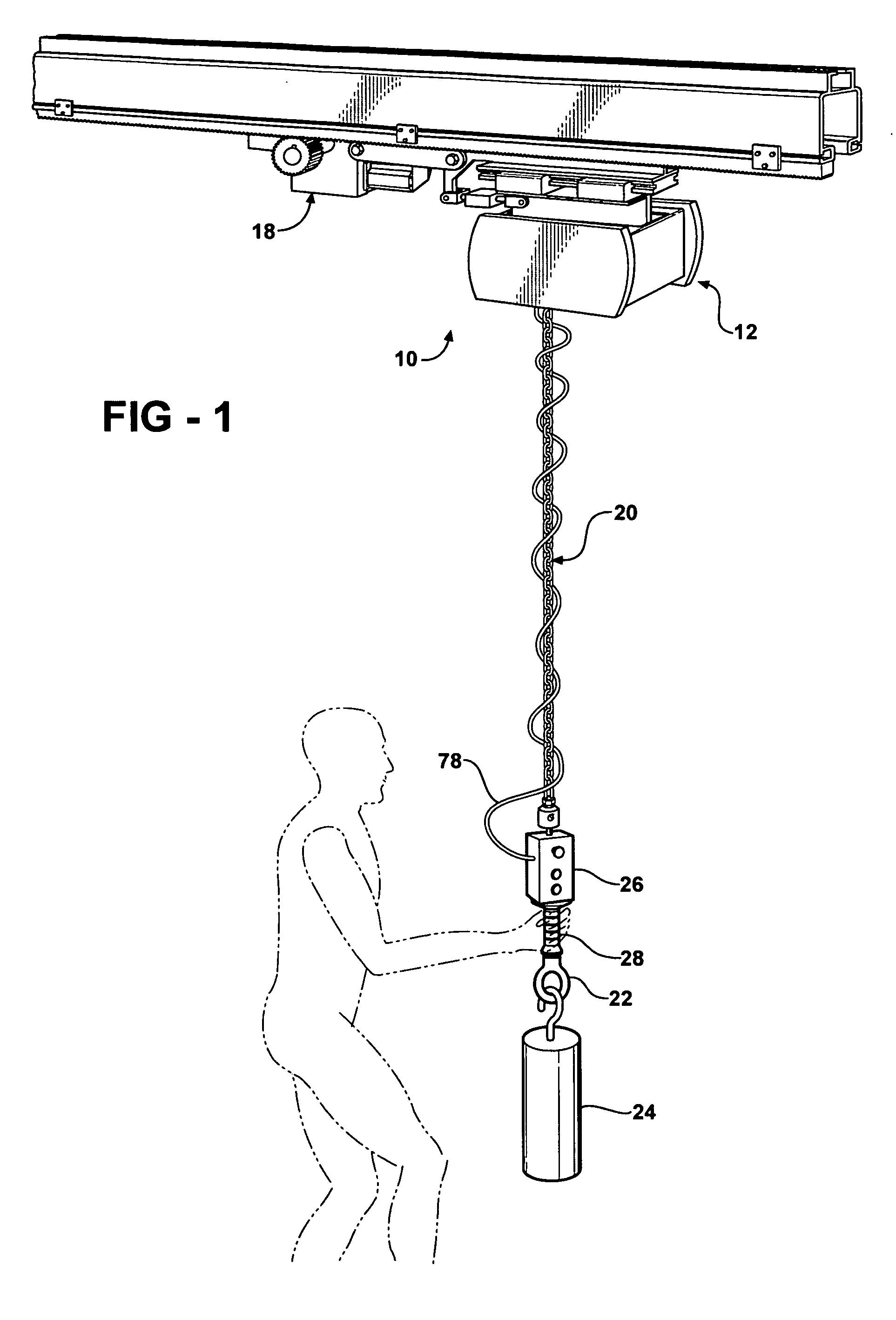
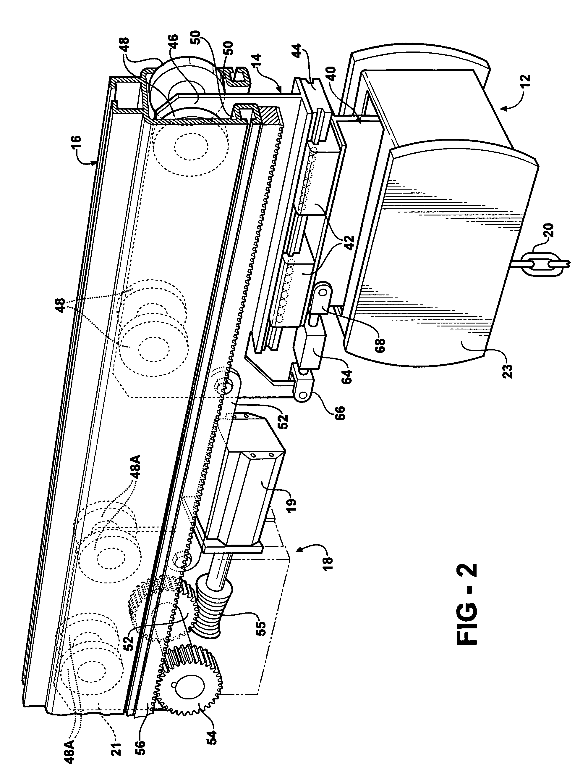
[0047] Referring to the drawings and particularly FIG. 1, a hoist system 10 according to the present invention includes an upper hoist assembly 12 supported on a trolley 14 able to be traversed along an overhead rail 16 by a trolley tractor drive 18 pulling its upper hoist assembly 12 when activated.

[0048] A hoist chain 20 is driven up and down by a chain drive arrangement in the upper hoist assembly 12, described below. The hoist chain 20 is connected to a lifting eye 22 on which the load 24 is hung.

[0049] A control grip 28 extends below the control box 26.

[0050] T...


PUM


Abstract

A balancer hoist has an electric servomotor driving irreversible gearing in turn driving a hoist chain drive. A float mode and a manual mode are provided using two independent load sensors for sensing the load weight and force applied to a control grip. A traversing control is produced by a tractor carriage rolling on an overhead rail connected to a trolley also traveling on the rail and supported on upper hoist assembly. A load sensor interconnects the tractor carriage and upon hoist assembly to sense forces created by an operator pulling on the chain, which are used to control an electric motor on the tractor carriage driving a pinion gear engaged with a gear rack on the overhead rail to positively drive the carriage, trolley and upper hoist assembly along the rail. A stationary dual hoist system is also described in which two hoist assemblies are interconnected by a chain and sprockets to provide synchronized operation.

Description

CROSS REFERENCE TO RELATED APPLICATION [0001] This application claims the benefit of provisional patent application Ser. No. 60 / 663,305, filed on Mar. 18, 2005.BACKGROUND OF THE INVENTION [0002] Balancing hoists have long been known in which a drum has a length of cable wound and unwound thereon as the drum is rotated in either direction to position a load held by the cable. This arrangement has utilized pneumatically operated hoists which use regulated air pressure acting on a piston to cause cable wind up or pay out by rotation of the drum. See U.S. Pat. No. 3,428,298 for a detailed description of this type of hoist. The load can be raised or lowered by the operator by exerting a low level force on the suspended load which increases or decreases the air pressure acting on the piston slightly, which pressure change is made up by a regulator to lower or raise the load accordingly. [0003] The limited stroke of the piston limits the cable travel that can be obtained, and thus electric...

Claims


Application Information

Patent Timeline
IPC IPC(8): B66C19/00
CPCB66D3/18B66C9/14
Inventor ZAGUROLI, JAMES JR.
Owner ZAGUROLI JR JAMES
Why Eureka
Try Eureka