
Speckle reduction in optical coherence tomography by path length encoded angular compounding

a technology of optical coherence tomography and path length, applied in the field of optical imaging methods and apparatus, to achieve the effect of facilitating a production of at least two radiations

Active Publication Date: 2006-10-12
THE GENERAL HOSPITAL CORP
View PDF99 Cites 25 Cited by
  • Summary
  • Abstract
  • Description
  • Claims
  • Application Information

AI Technical Summary

Benefits of technology

[0007] According to one exemplary embodiment of the present invention, a method for performing angular compounding to :reduce speckle within OCT images is provided, which may use angular compounding by path length encoding (“ACPE”). With ACPE, a high-speed acquisition can be maintained, and modifications to standard OCT catheter optics are likely to be minimal. In another exemplary embodiment according to the present invention, an apparatus for imaging is provided that uses ACPE.
[0008] Accordingly, apparatus probe catheter, and method according to exemplary embodiments of the present invention are provided for irradiating a sample. In particular, an interferometer may forward forwarding an electromagnetic radiation. In addition, a sample arm may receive the electromagnetic radiation, and can include an arrangement which facilitates a production of at least two radiations from the electromagnetic radiation so as to irradiate the sample. Such arrangement can be configured to delay a first radiation of the at least two radiations with respect to a second radiation of the at least two radiations.
[0012] According to yet another exemplary embodiment of the present invention, an apparatus for imaging is provided. The apparatus includes a sample arm that receive an electromagnetic radiation. The sample arm includes an arrangement which facilitates a production of at least two radiations from the electromagnetic radiation so as to irradiate a sample. The arrangement is configured to delay a first radiation of the at least two radiations with respect to a second radiation of the at least two radiations. The apparatus also includes a device for receiving the first and second radiations from the sample arm and at least one third radiation from a reference arm, such that the first and second radiations interfere with the third radiation. Further, the apparatus includes at least one of spectral separating unit which separates spectrum of at least one of the first, second and third radiations into frequency components, and at least one detection arrangement including a plurality of detectors. Each detector is capable of detecting at least a portion of at least one of the frequency components.
[0013] In a further exemplary embodiment of the present invention, an apparatus is provided. Such apparatus includes at least one first arrangement that provides at least one first electromagnetic radiation to a sample arm and at least one second electromagnetic radiation to a non-reflective reference arm. A frequency of radiation provided by the first arrangement varies over time. The sample arm receives the first electromagnetic radiation, and includes an arrangement which facilitates a production of at least two radiations from the electromagnetic radiation so as to irradiate a sample. The arrangement is configured to delay a first radiation of the at least two radiations with respect to a second radiation of the at least two radiations. The apparatus also includes at least one second arrangement detecting an interference between the first and second radiations generated at the sample arm and the second electromagnetic radiations generated at the reference.
[0014] In still another exemplary embodiment of the present invention, an apparatus is provided. The apparatus includes a at least one first arrangement providing at least one first electromagnetic radiation to a sample arm and at least one second electromagnetic radiation to a reference arm. The first and / or second electro-magnetic radiation have a spectrum which changes over time. The spectrum contains multiple frequencies at a particular time. The sample arm receives the first electromagnetic radiation, and includes an arrangement which facilitates a production of at least two radiations from the electromagnetic radiation so as to irradiate a sample. The arrangement is configured to delay a first radiation of the at least two radiations with respect to a second radiation of the at least two radiations. The apparatus also includes at least one second arrangement detecting an interference between the first and second radiations generated at the sample arm and the second electromagnetic radiations generated at the reference.

Problems solved by technology

In addition, the further image may have a noise that is smaller than a noise of the first image and a noise of the second image.

Method used


Image

  • Speckle reduction in optical coherence tomography by path length encoded angular compounding
  • Speckle reduction in optical coherence tomography by path length encoded angular compounding
  • Speckle reduction in optical coherence tomography by path length encoded angular compounding

Examples


example 1

II. Example 1

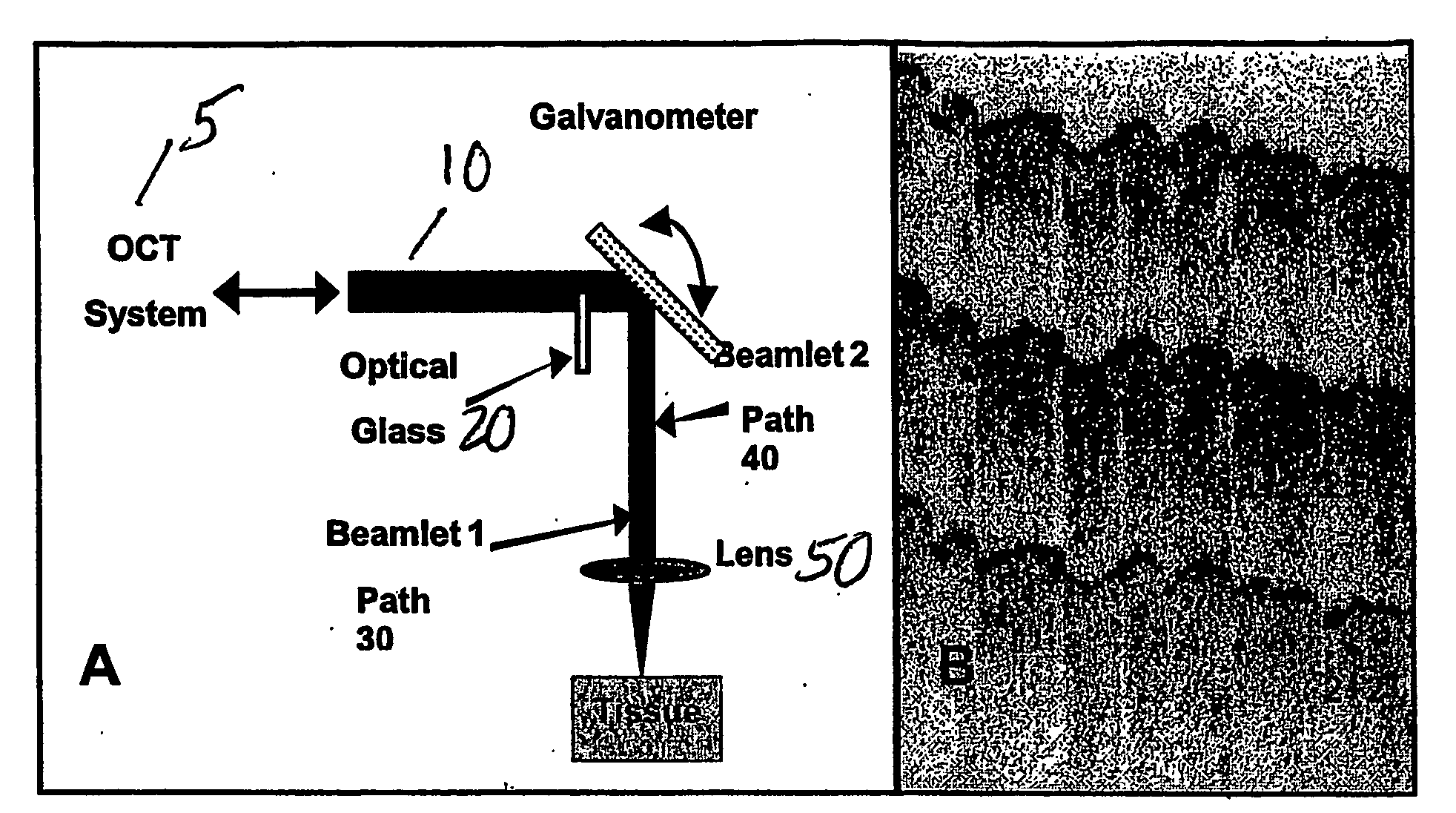
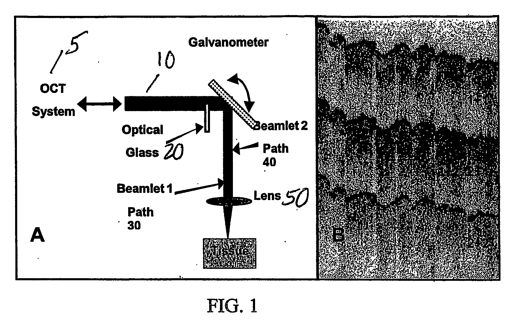
[0026] An exemplary polarization-diverse OCT system according to the present invention can be utilized for the examplary apparatus (e.g., as shown in FIG. 1A) that implements ACPE. Using such exemplary system according to the present invention, OCT images may be acquired at 2 frames per second (e.g., 500 axial pixels×500 transverse pixels), which may be displayed with an inverse gray-scale lookup table, and digitally archived. The optical source which can be used in such exemplary OCT system may have a center wavelength of 1310 nm and a bandwidth of 70 nm, and thus providing an axial resolution of approximately 8 μm in the tissue.

[0027] A modified hand-held galvanometer probe (e.g., the apparatus of FIG. 1A) can be inserted in the sample arm of the OCT system 5. The objective lens 50 may have a focal length of 25 mm and a numerical aperture (NA) of 0.11, providing a measured 1 / e2 focal spot diameter of 23 μm. A square, antireflection-coated D=3.1 mm BK7 glass (n=1.51) ...

example 2

III. Example 2

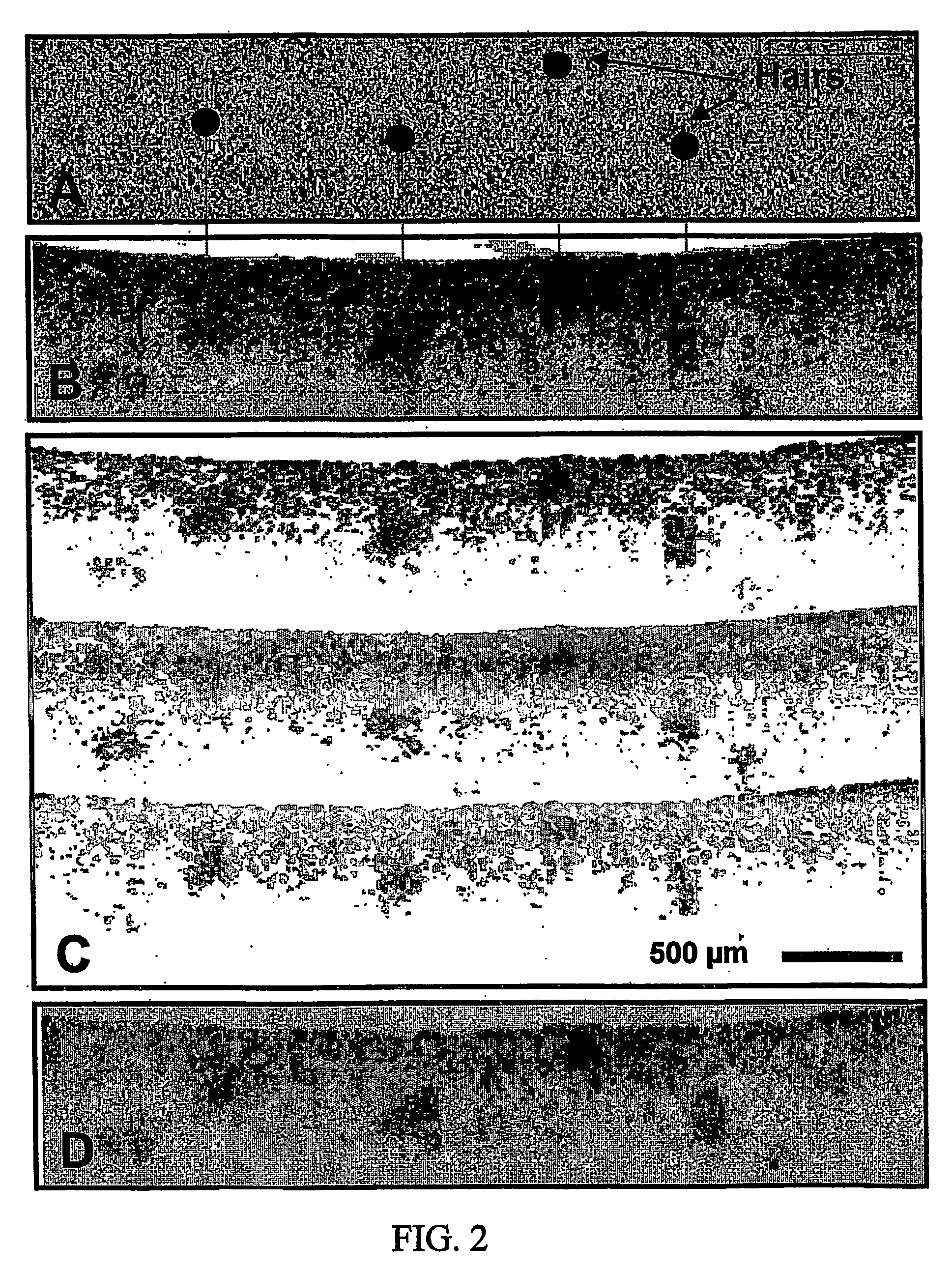
[0028] A solid phantom consisting of 1% Intralipid solution and Agar can be used to measure a reduction in speckle provided by ACPE. For example, four (4) hairs can be embedded in the Intralipid-Agar gel at different transverse positions and depths. A schematic of the phantom is depicted in FIG. 2A. The corresponding OCT images with and without the BK7 glass plate are shown in FIGS. 2B and 2C, respectively. ROI's labeled 1-5 represent exemplary locations where the SNR improvement by ACPE is preferably measured. The insertion of the BK7 glass plate 20 (with a 3.1 mm BK7 glass element) in the sample arm can produce three copies of the original OCT image (see FIG. 2C), with each image being acquired at a different illumination angles and separated by group delay increments of, e.g., 800 μm. The amplitudes of the signals in the top and bottom images of FIG. 2C can be approximately half of the center image (S1OCT / S2OCT=S3OCT / S2OCT=1:2). The compounded ACPE image shown in FI...

example 3

IV. Example 3

[0029] In order to demonstrate SNR improvement in vivo, ACPE OCT imaging can be performed on a ventral forearm of a subject. FIGS. 3A and 3B shows one representative set of images. FIG. 3A shows an exemplary OCT image of the ventral forearm obtained in vivo prior to the insertion of the BK7 ACPE element. Visual assessment of these pictures demonstrates a qualitative improvement in the compounded ACPE image (FIG. 3B). The boundary between the epidermis (E) and dermis (D) is more clearly demarcated with ACPE as shown in FIG. 3B. In addition, horizontal structures consistent with dermal vasculature are more readily identified in the ACPE image of FIG. 3B. The SNR can be measured for the ACPE and original OCT images in FIG. 3B, providing an exemplary SNR improvement of 1.56.

[0030] The apparatus and method according to the exemplary embodiments of the present invention are provide to reduce speckle in OCT images that does not decrease the OCT frame rate and requires only mi...


PUM


Abstract

Speckle, a factor reducing image quality in optical coherence tomography (“OCT”), can limit the ability to identify cellular structures that are important for the diagnosis of a variety of diseases. The present invention allows for an implementation of an angular compounding, angular compounding by path length encoding (“ACPE”) for reducing speckle in OCT images. By averaging images obtained at different incident angles, with each image encoded by path length, ACPE maintains high-speed image acquisition and implements minimal modifications to OCT probe optics. ACPE images obtained from tissue phantoms and human skin in vivo demonstrate a qualitative improvement over traditional OCT and an increased signal-to-noise ratio (“SNR”). Accordingly, apparatus probe catheter, and method are provided for irradiating a sample. In particular, an interferometer may forward forwarding an electromagnetic radiation. In addition, a sample arm may receive the electromagnetic radiation, and can include an arrangement which facilitates a production of at least two radiations from the electromagnetic radiation so as to irradiate the sample. Such arrangement can be configured to delay a first radiation of the at least two radiations with respect to a second radiation of the at least two radiations.

Description

CROSS-REFERENCE TO RELATED APPLICATIONS [0001] The present application claims priority from U.S. patent application Ser. No. 60 / 459,543 filed on on Mar. 31, 2003, International Patent Application No. PCT / US03 / 02349 filed on Jan. 24, 2003, and U.S. Patent Applications Ser. Nos. 60 / 476,600, 60 / 514,769, filed on Jun. 6, 2003 and Oct. 27, 2003, respectively, the entire disclosures of which are incorporated herein by reference.FIELD OF THE INVENTION [0002] The present invention relates to optical imaging methods and apparatus useful in medical diagnosis and imaging. In particular, the present invention relates to a high speed method for implementing angular compounding, e.g., angular compounding by path length encoding (“ACPE”) for reducing speckle in optical coherence tomography images. BACKGROUND INFORMATION [0003] Optical coherence tomography (“OCT”) is a technique for obtaining high resolution cross-sectional images of biological tissues. Clinical OCT studies conducted in the gastroi...

Claims


Application Information

Patent Timeline
IPC IPC(8): G01B11/02A61B5/00G01J9/02G01N21/47G02B27/48
CPCA61B5/0059A61B5/0066A61B5/6852G01J9/0215G01N21/4795G01B9/02082G02B27/48G01B9/02028G01B9/02091G01B9/02087G02B26/105
Inventor TEARNEY, GUILLERMO J.IFTIMIA, NICUSORBOUMA, BRETT EUGENE
Owner THE GENERAL HOSPITAL CORP
Learn More