Method for dynamic insertion loss control for 10/100/1000 mhz ethernet signaling

Active Publication Date: 2006-10-26
KINETIC TECH INT HLDG LP
View PDF4 Cites 108 Cited by
  • Summary
  • Abstract
  • Description
  • Claims
  • Application Information

AI Technical Summary

Benefits of technology

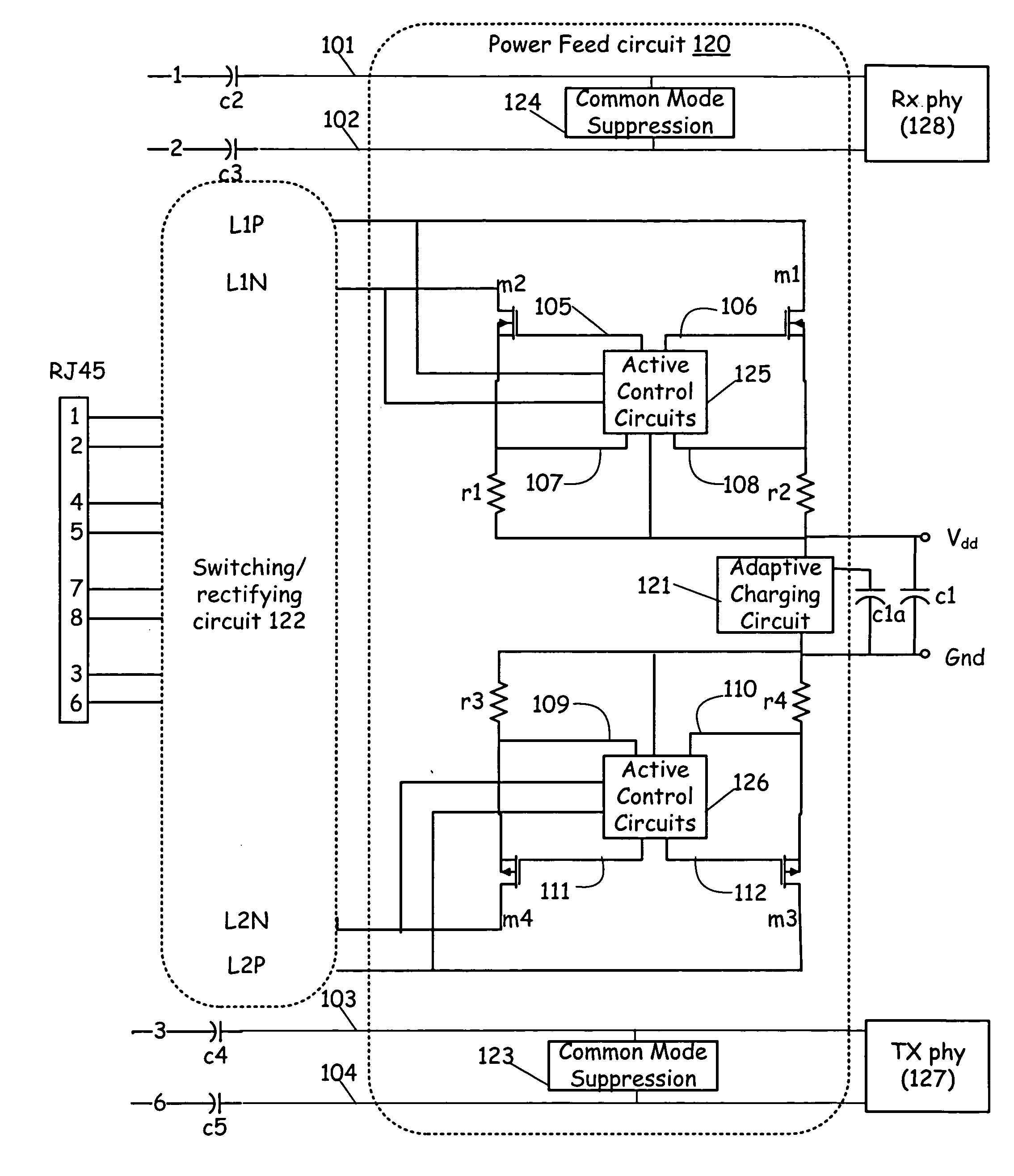
[0011] Another embodiment provides a power feed circuit operable to supply power to at least a portion of an Ethernet (i.e. network-attached) PD. This power feed circuit includes two differential transistor pairs, two pairs of differential impedances, insertion loss control circuit(s), a common-mode feedback amplifier, a differential amplifier, and a pair of output nodes. The two differential transistor pairs each are operable to receive and pass an Ethernet power signal. The differential impedances each individually couple to a differential transistor drain. The differential impedances pass the Ethernet power signal and produce an input voltage to the differential amplifier. The insertion loss control circuit provides an insertion loss limit to a common-mode feedback amplifier. Then the common-mode feedback amplifier senses an average Ethernet power signal and produces a common-mode feedback signal. The differential amplifier receives the common-mode feedback signal and the differential voltage across the differential impedances. The differential amplifier then produces and applies a control o

Problems solved by technology

Additionally, power distributed over a network such as an Ethernet network may provide an uninterruptible power supply (UPS) to key components or devices that normally would require a dedicated UPS.
One drawback of VOIP telephony is that in the event of a power failure, the ability to contact to emergency services via an independently powered telephone is removed.
However, these power distribution schemes within a network environment typically require cumbersome, real estate intensive, magnetic transformers.
Additionally, power over Ethernet (PoE) requirements under 802.3 are quite string

Method used


Image

  • Method for dynamic insertion loss control for 10/100/1000 mhz ethernet signaling
  • Method for dynamic insertion loss control for 10/100/1000 mhz ethernet signaling
  • Method for dynamic insertion loss control for 10/100/1000 mhz ethernet signaling

Examples


Embodiment Construction

[0031] Preferred embodiments of the present invention are illustrated in the FIGs., like numerals being used to refer to like and corresponding parts of the various drawings.

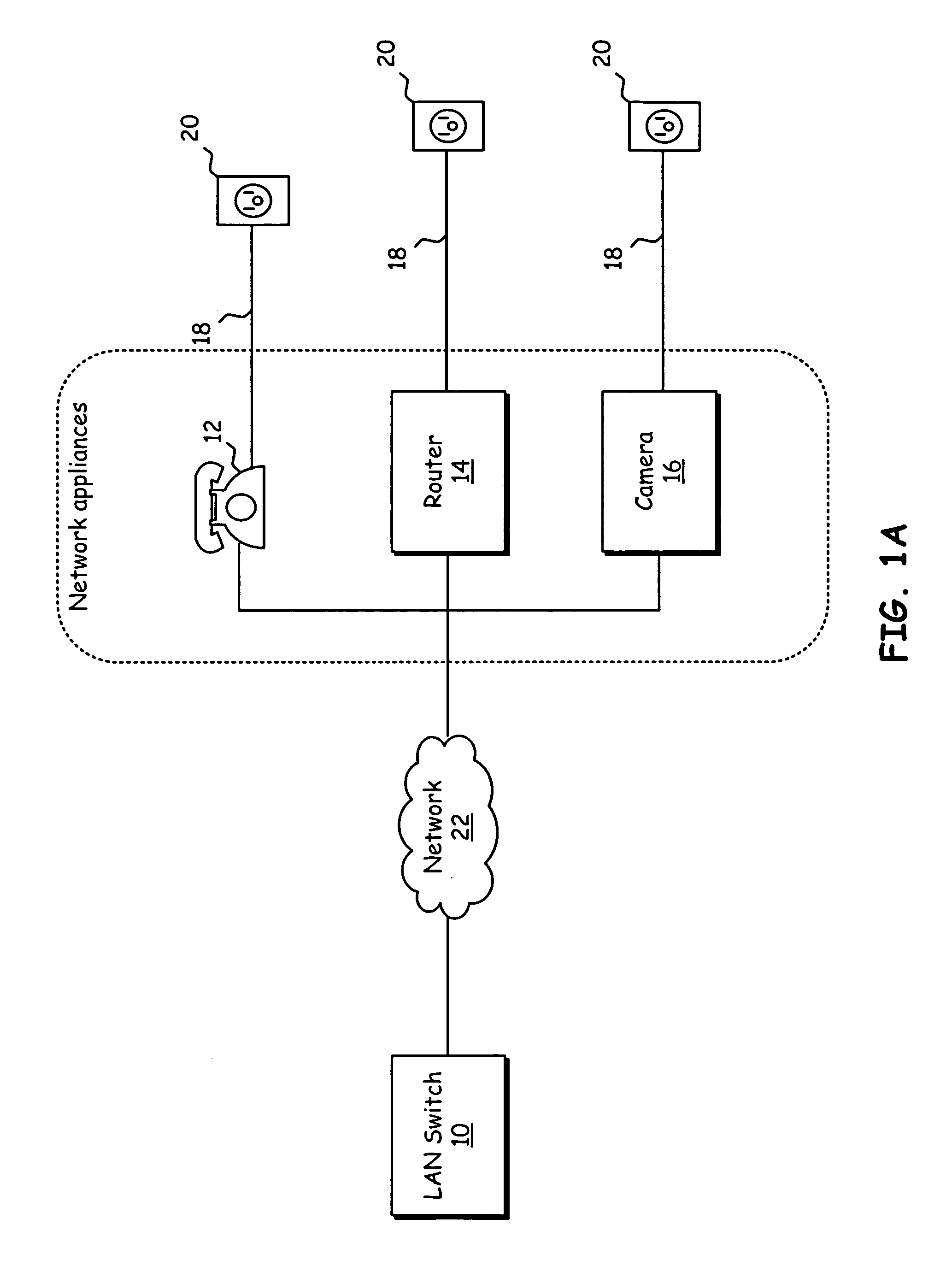
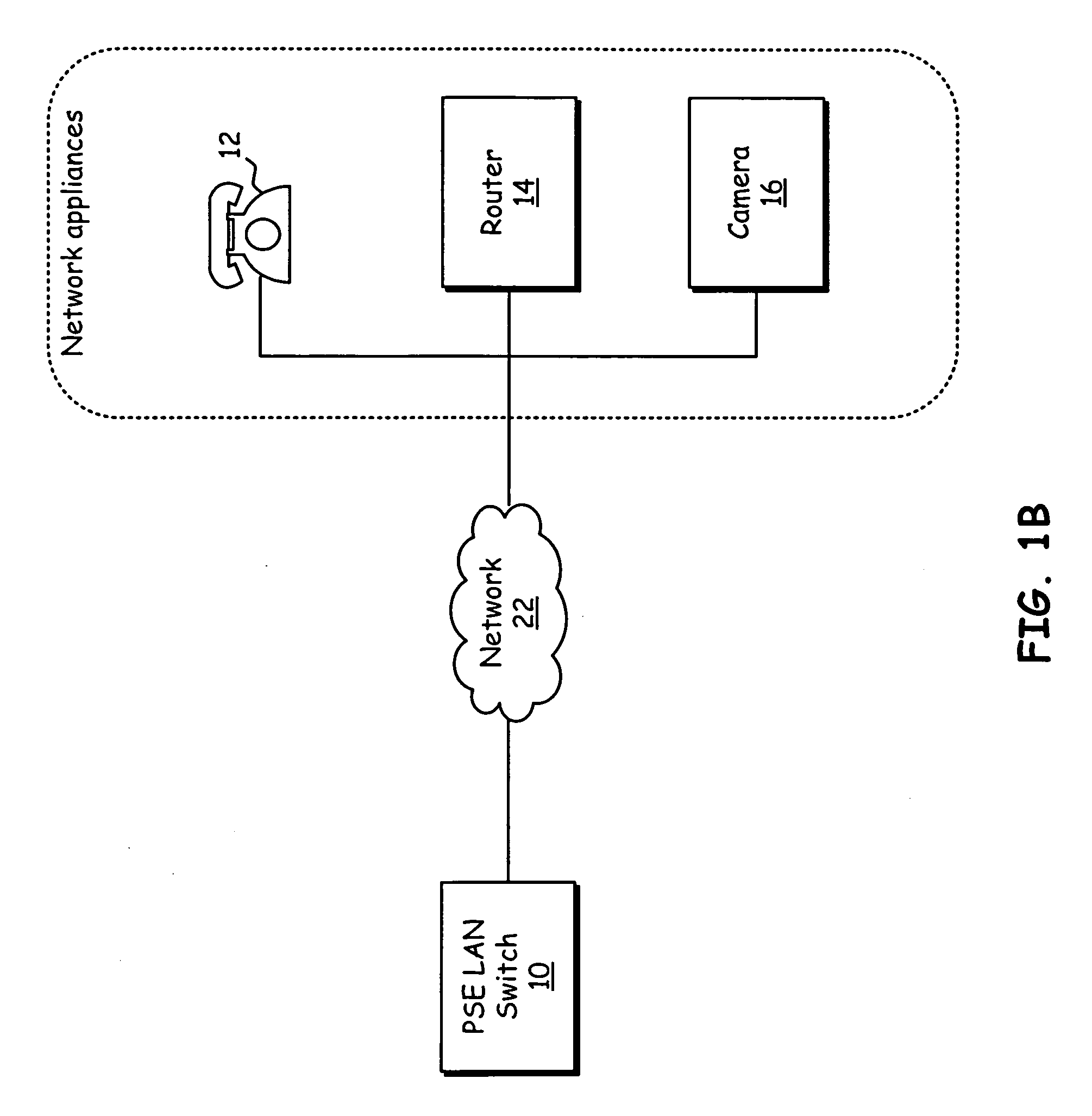
[0032] The 802.3 Ethernet network Standards, which is incorporated herein by reference, allow loop powering of remote Ethernet network devices (802.3). The Power over Ethernet (PoE) standard and other like standards intends to standardize the delivery of power over Ethernet network cables in order to have remote client devices powered through the network connection. The side of link that supplies the power is referred to as Powered Supply Equipment (PSE). The side of link that receives the power is referred to as the Powered device (PD).

[0033] Replacing the magnetic transformer of prior PoE systems while maintaining the functionality of the transformer has been subsumed into the embodiments of the present invention. In order to subsume the functionality of the transformer, the circuits provided by embodiments ...


PUM


Abstract

The present invention provides for dynamic insertion loss control for a 10/100/1000 megahertz Ethernet power on differential cable pairs. A power feed circuit supplies power to a network attached device (PD). An insertion loss control circuit limits power loss in a coupled power feed circuit. The insertion loss control circuit determines an insertion loss limit and senses an average power of the power signals to produce a common mode feedback signal to the power feed circuit. The insertion loss limit is determined for the received signals based on a differential RMS of the received Ethernet power signals as seen by a differential transistor pair. Alternatively, the insertion loss limit may be determined logically by the higher layers of the network protocol based on the AC differential portion of the network power signal. When the insertion loss limit is determined based on the differential RMS, the insertion loss control circuit is operable to automatically reduce the insertion loss based upon transmission losses experienced over the network connection between the power sending equipment and network-attached device.

Description

CROSS REFERENCE TO RELATED APPLICATIONS [0001] This application claims the benefit of priority to and incorporates herein by reference in its entirety for all purposes, U.S. Provisional Patent Application No. 60 / 665,766 entitled “SYSTEMS AND METHODS OPERABLE TO ALLOW LOOP POWERING OF NETWORKED DEVICES,” by John R. Camagna, et al. filed on Mar. 28, 2005. This application is related to and incorporates herein by reference in its entirety for all purposes, U.S. patent application Ser. Nos.: XX / XXX,XXX entitled “SYSTEMS AND METHODS OPERABLE TO ALLOW LOOP POWERING OF NETWORKED DEVICES,” by John R. Camagna, et al.; XX / XXX,XXX entitled “METHOD FOR HIGH VOLTAGE POWER FEED ON DIFFERENTIAL CABLE PAIRS,” by John R. Camagna, et al., which have been filed concurrently.TECHNICAL FIELD OF THE INVENTION [0002] The present invention relates generally to power distribution, and more particularly to reducing inefficiencies associated with distributing power over a high bandwidth network. BACKGROUND OF...

Claims


Application Information

Patent Timeline
IPC IPC(8): H03F3/45
CPCH03F1/02H03F1/52H04L12/10H03F3/45632H03F3/45179
Inventor CAMAGNA, JOHN R.CRAWLEY, PHILLIP JOHN
Owner KINETIC TECH INT HLDG LP
Why Eureka
Try Eureka