[0022] The invention relates to an improved microfinishing process for the use on component parts for the automotive,
diesel engine,
aerospace, hydraulic and medical devices and many other precision industries. This electrolytic microfinishing process uses
solid abrasives to
machine geometric accuracies by generating the form which improves or creates surface finished not previously achieved by any other machining method known to date. The electrolytic microfinishing process allows faster
material removal, better surface finishes, burr-free surfaces, significantly reduced holding or
contact pressure between the tool and workpiece results in reduced
tool wear, reduced
cycle time by over 50% of the conventional microfinishing process while creating an abrasive free finished surface. Electrolytic microfinishing machines closely resemble conventional microfinish machines in both appearance and to some degree operation. For example, the tool in all cases, looks just like the conventional abrasive stone, except that the stone contains
electrically conductive bonding material to hold the abrasive together. The
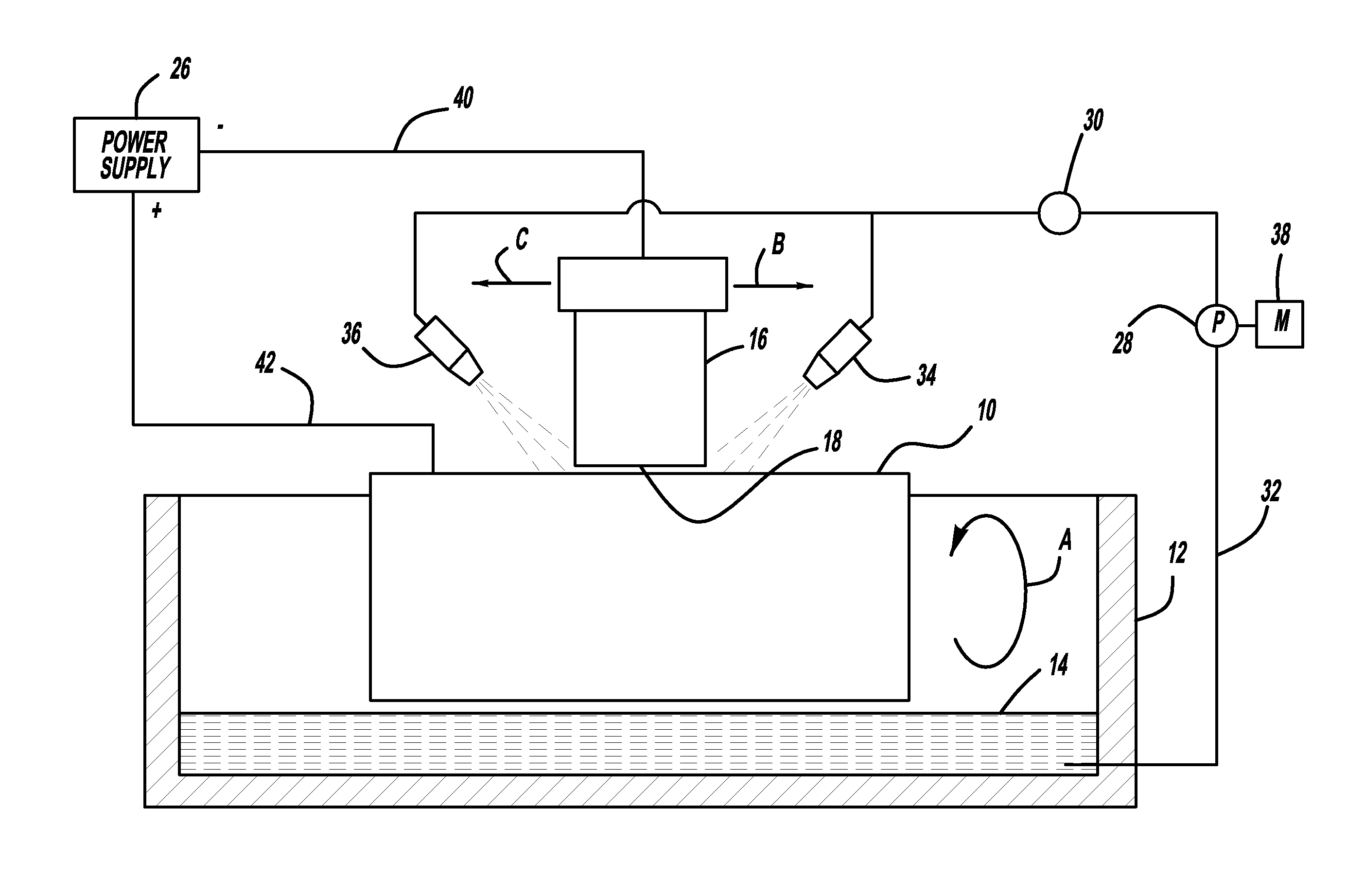
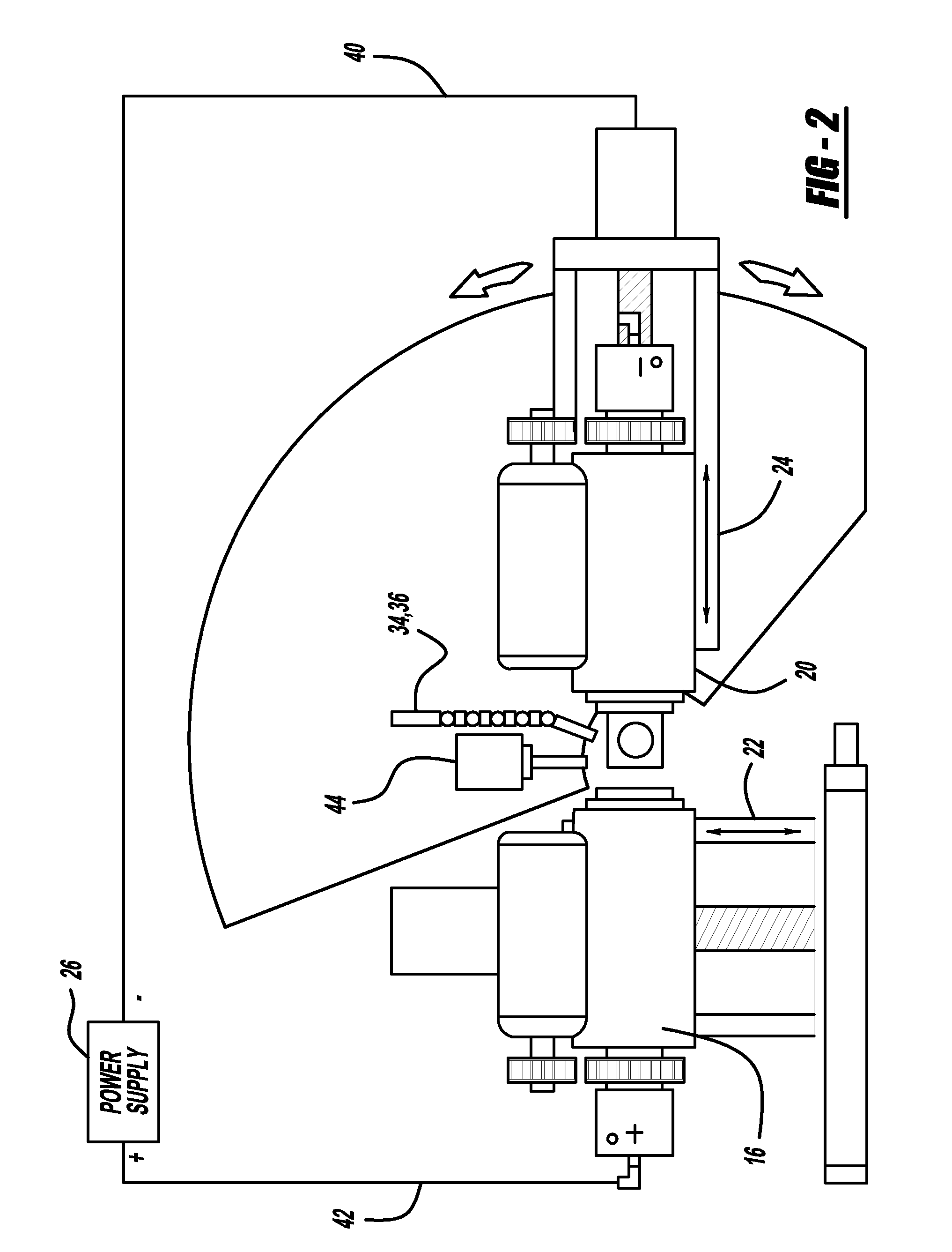
electrolyte that is used is introduced to the wheel in much the same matter as conventional coolants used in any machining operation. A housing is provided to contain the electrolytic solution. The installation also requires a power supply, a very simple pumping
station with the appropriate
filtration system to provide the
electrolyte from an electrolyte reservoir to the workpiece to be microfinished. Since both the work spindle and tool spindle have been electrically isolated, in operation, the workpiece becomes a positive pole and the tool becomes a negative pole in the
direct current circuit. When the
current source is switched on, the material of the workpiece is decomposed or dissolved by the electrolyte, which is pumped between the rotating surfaces of the tool and workpiece. The rotating tool near the workpiece results in the tool carrying the electrolyte into the
cut which brings about the electrochemical action on the workpiece.
Metal removal is largely brought about by non-mechanical action, since the
contact pressure between the tool and the workpiece is only a fraction of the pressure used in conventional microfinishing. Thus, the need for frequent dressing of the tool is eliminated. The
metal removal rate is largely governed by the amount of
electric power and electrolyte applied, regardless of the material's
hardness. Because of the dissolving action and relative absence of both heat and tool contact, the electrolytic microfinishing process is ideal for fast
stock removal of parts that cannot stand thermal machining damage, as well as result in extremely
smooth surface finishes. By eliminating contact between the tool and workpiece, the risk of transfer of abrasive particles from the tool to the workpiece is completely eliminated, thereby ensuring an abrasive free microfinished surface on the workpiece. This invention is ideally practiced as a final machining step on a workpiece with a surface to be finished by reducing or eliminating one or more
metal cutting or machining steps, i.e., turning and / or
grinding of a conventional nature. A programmable microfinish process controller monitors the various process parameters using sensors to obtain the optimum performance from each of the process elements.

