MEMS bubble generator

a technology of vapor bubbles and generators, which is applied in printing, other printing apparatus, inking apparatus, etc., can solve the problems of reducing the efficiency of the device, the resistance heaters of inkjet printheads operating in an extremely harsh environment, and the formation of a rapidly expanding vapor bubble, etc., to achieve the effect of reducing the density of grain boundaries, good material strength, and high density of grain boundaries

Active Publication Date: 2006-11-09
SILVERBROOK RES PTY LTD
View PDF13 Cites 61 Cited by
  • Summary
  • Abstract
  • Description
  • Claims
  • Application Information

AI Technical Summary

Benefits of technology

[0042] A grain size less than 100 nm (a “nanocrystalline” microstructure) is beneficial in that it provides good material strength yet has a high density of grain boundaries. Compared to a material with much larger crystals and a lower density of grain boundaries, the nanocrystalline structure provides higher diffusivity for the protective scale forming elements Cr and Al (more rapid formation of the scale) and a more even growth of the scale over the heater surface, so the protection is provided more rapidly and more effectively. The protective scales adhere better to the nanocrystalline structure, which results in reduced spalling. Further improvement in the mechanical stability and adherence of the scale is possible using additives of reactive metal from the group consisting of yttrium, lanthanum and

Problems solved by technology

In one class of these liquid-containing devices, resistive heaters are used to heat the liquid to the liquid's superheat limit, resulting in the formation of a rapidly expanding vapor bubble.
The resistive heaters in inkjet printheads operate in an extremely harsh environment.
Heating this additional volume decreases the efficiency of the device and significantly increases the level of residual heat present after firing.
If this additional heat cannot be removed between successive firings of the nozzle, the ink in the nozzles will boil continuously, causing the nozzles to ce

Method used


Image

  • MEMS bubble generator
  • MEMS bubble generator
  • MEMS bubble generator

Examples


Embodiment Construction

[0093] In the description than follows, corresponding reference numerals, or corresponding prefixes of reference numerals (i.e. the parts of the reference numerals appearing before a point mark) which are used in different figures relate to corresponding parts. Where there are corresponding prefixes and differing suffixes to the reference numerals, these indicate different specific embodiments of corresponding parts.

OVERVIEW OF THE INVENTION AND GENERAL DISCUSSION OF OPERATION

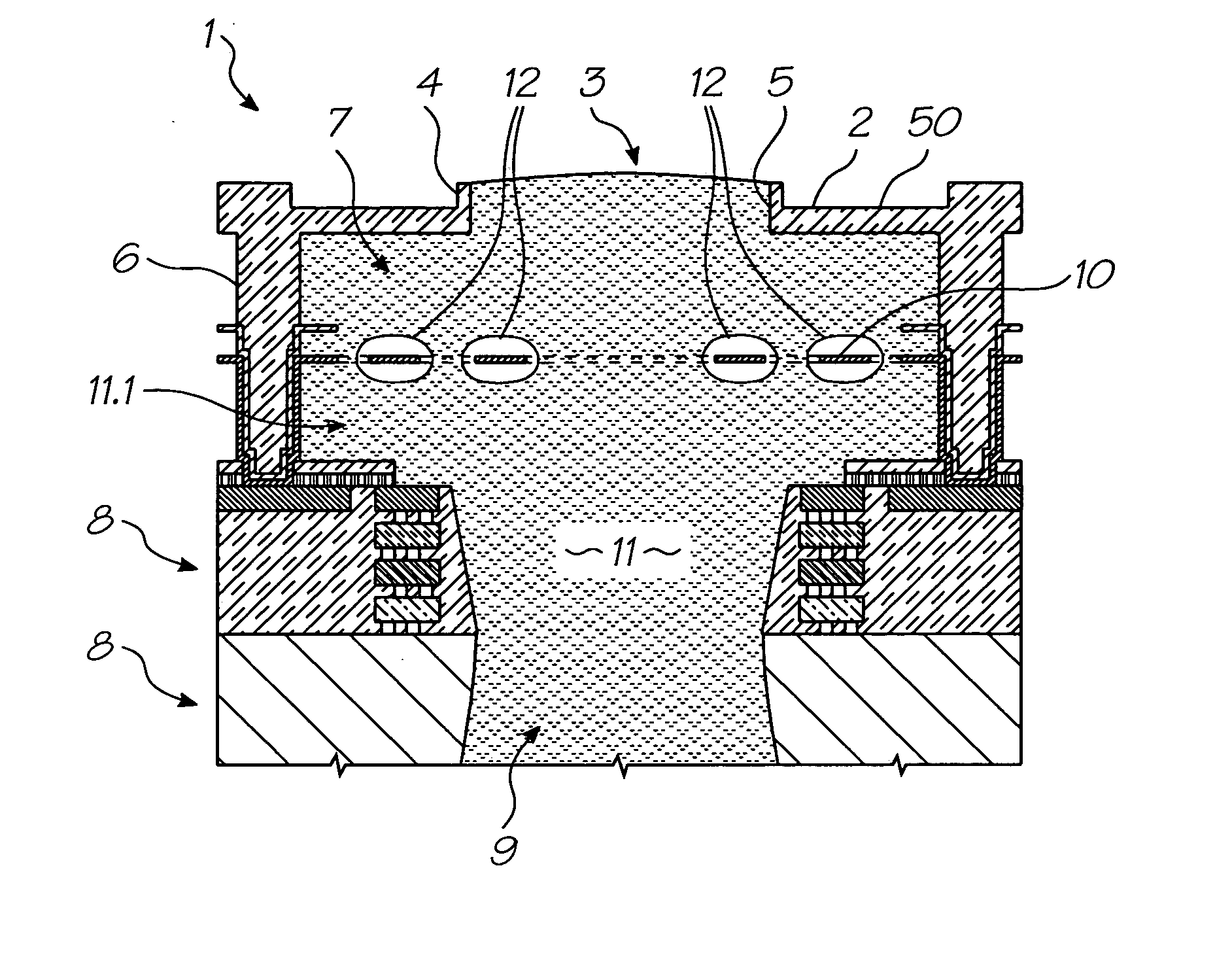
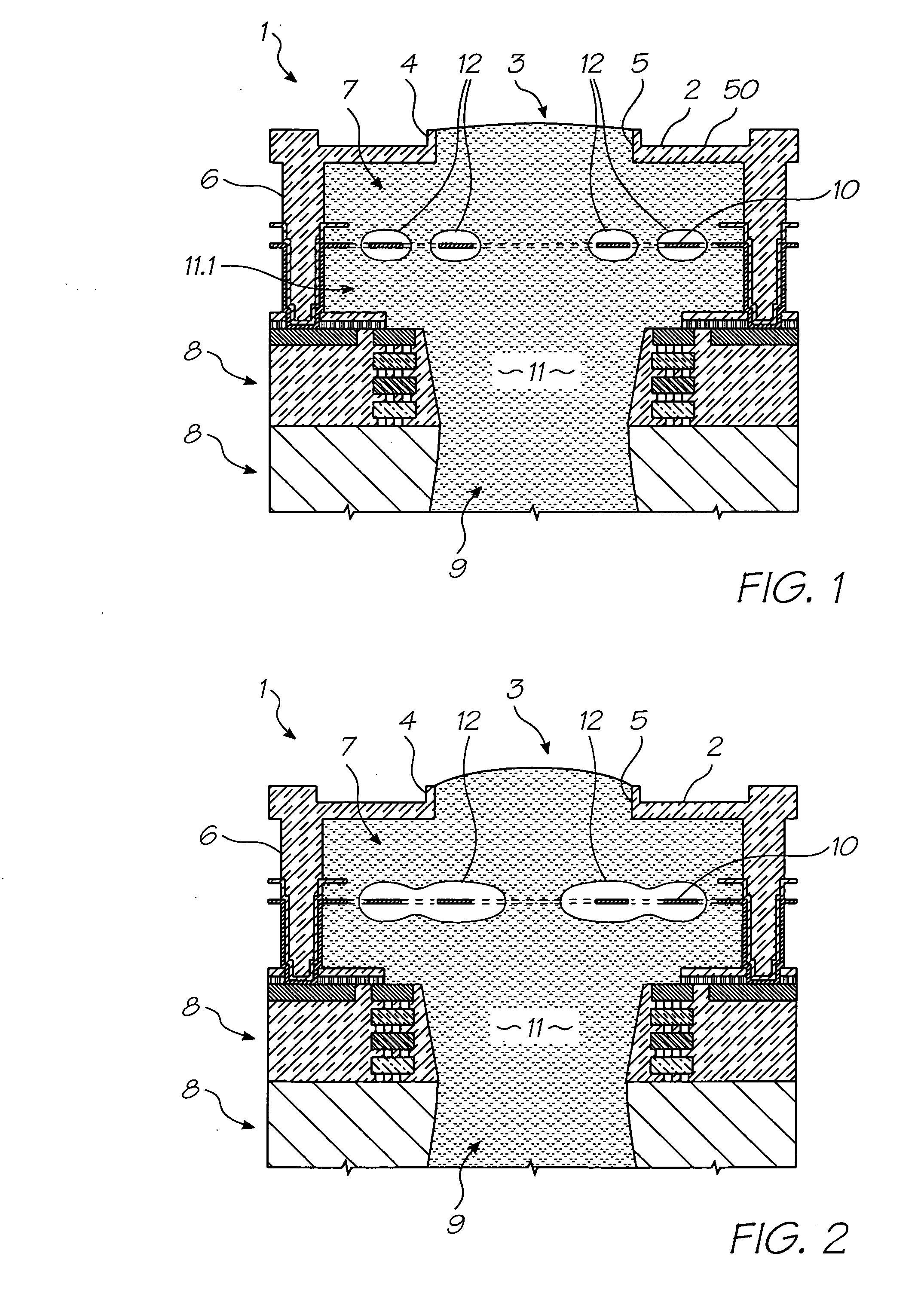
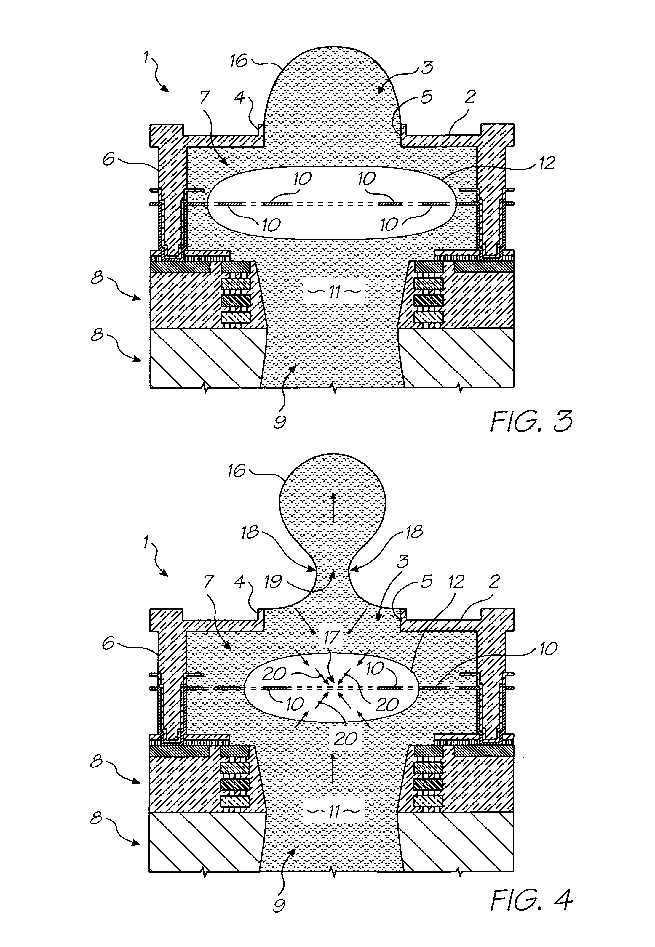
[0094] With reference to FIGS. 1 to 4, the unit cell 1 of a printhead according to an embodiment of the invention comprises a nozzle plate 2 with nozzles 3 therein, the nozzles having nozzle rims 4, and apertures 5 extending through the nozzle plate. The nozzle plate 2 is plasma etched from a silicon nitride structure which is deposited, by way of chemical vapor deposition (CVD), over a sacrificial material which is subsequently etched.

[0095] The printhead also includes, with respect to each nozzle 3, side w...


PUM


Abstract

A MEMS vapor bubble generator with a chamber for holding liquid and a heater positioned in the chamber for heating the liquid above its bubble nucleation point to form a vapour bubble; wherein, the heater is formed from a superalloy.

Description

CROSS REFERENCE TO RELATED APPLICATION [0001] The present application is a Continuation-In-Part of U.S. application Ser. No. 11 / 097308 filed on Apr. 4, 2005, the entire contents of which are now incorporated by reference. [0002] Various methods, systems and apparatus relating to the present invention are disclosed in the following US Patents / Patent Applications filed by the applicant or assignee of the present invention: 09 / 517539656685863319466246970644252509 / 51738409 / 505951637435409 / 517608681696867578326334190674533109 / 51754110 / 20355910 / 20356010 / 20356410 / 63626310 / 63628310 / 86660810 / 90288910 / 90283310 / 94065310 / 94285810 / 72718110 / 72716210 / 72716310 / 72724510 / 72720410 / 72723310 / 72728010 / 72715710 / 72717810 / 72721010 / 72725710 / 72723810 / 72725110 / 72715910 / 72718010 / 72717910 / 72719210 / 72727410 / 72716410 / 72716110 / 72719810 / 72715810 / 75453610 / 75493810 / 72722710 / 72716010 / 93472011 / 21270211 / 27249110 / 296522679521510 / 29653509 / 5751096805419685928969777516398332639457366229236747760692114410 / 88488110 / 94394110 / 9...

Claims


Application Information

Patent Timeline
IPC IPC(8): B41J2/05
CPCB41J2/1412B41J2/1601B41J2/1603B41J2/1628B41J2/1631B41J2202/03B41J2/1645B41J2/1646B41J2002/1437B41J2002/14403B41J2002/14475B41J2/1639
Inventor SILVERBROOK, KIAFOOTE, ROGER MERVYN LLOYDNORTH, ANGUS JOHNFISHBURN, JENNIFER MIALUNSMANN, PAUL DAVIDPAPADAKIS, ALEXANDRA ARTEMISC.S., LAKSHMICROUS, FREDERIK JACOBUSWALKER, MATTHEW STEWART
Owner SILVERBROOK RES PTY LTD
Why Eureka
Try Eureka