Dynamic semiconductor storage device
- Summary
- Abstract
- Description
- Claims
- Application Information
AI Technical Summary
Benefits of technology
Problems solved by technology
Method used
Image
Examples
first embodiment
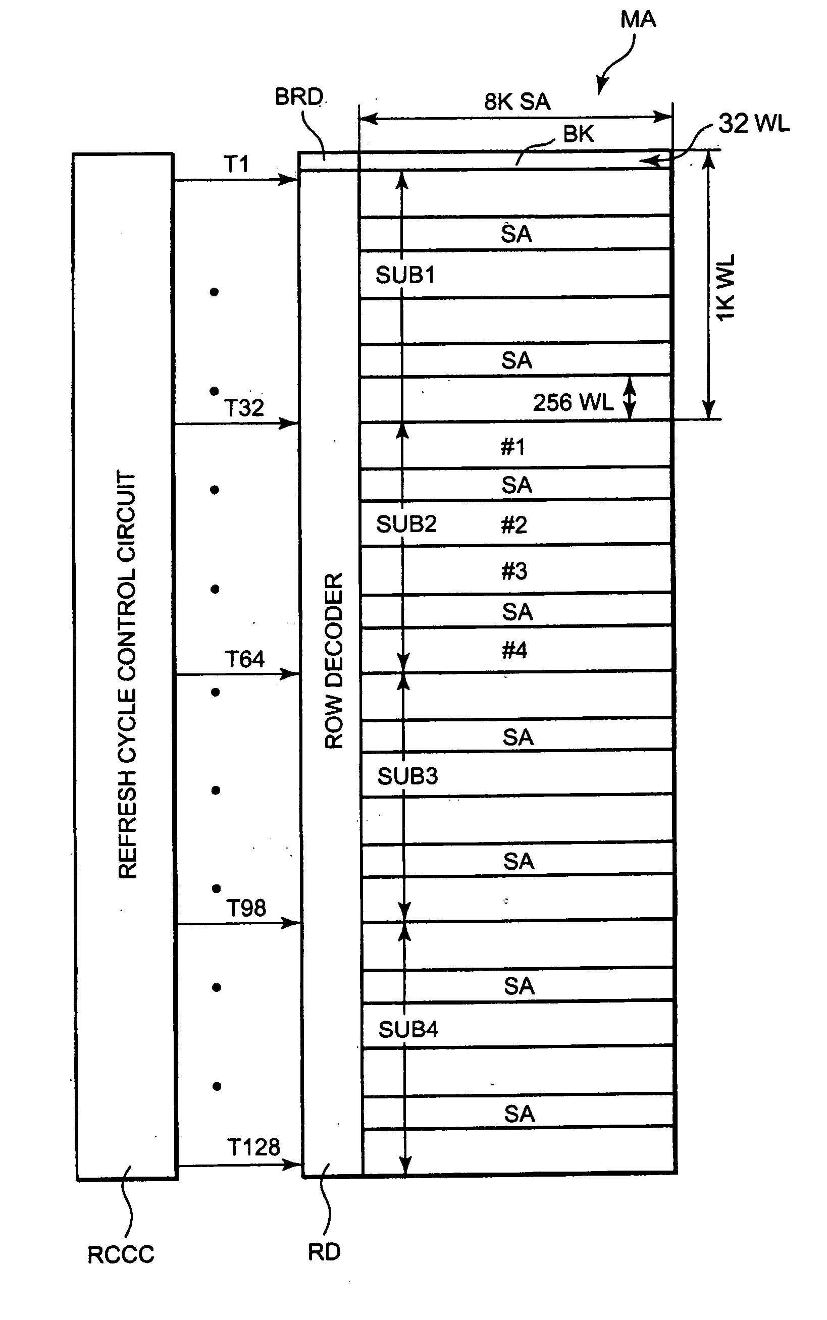
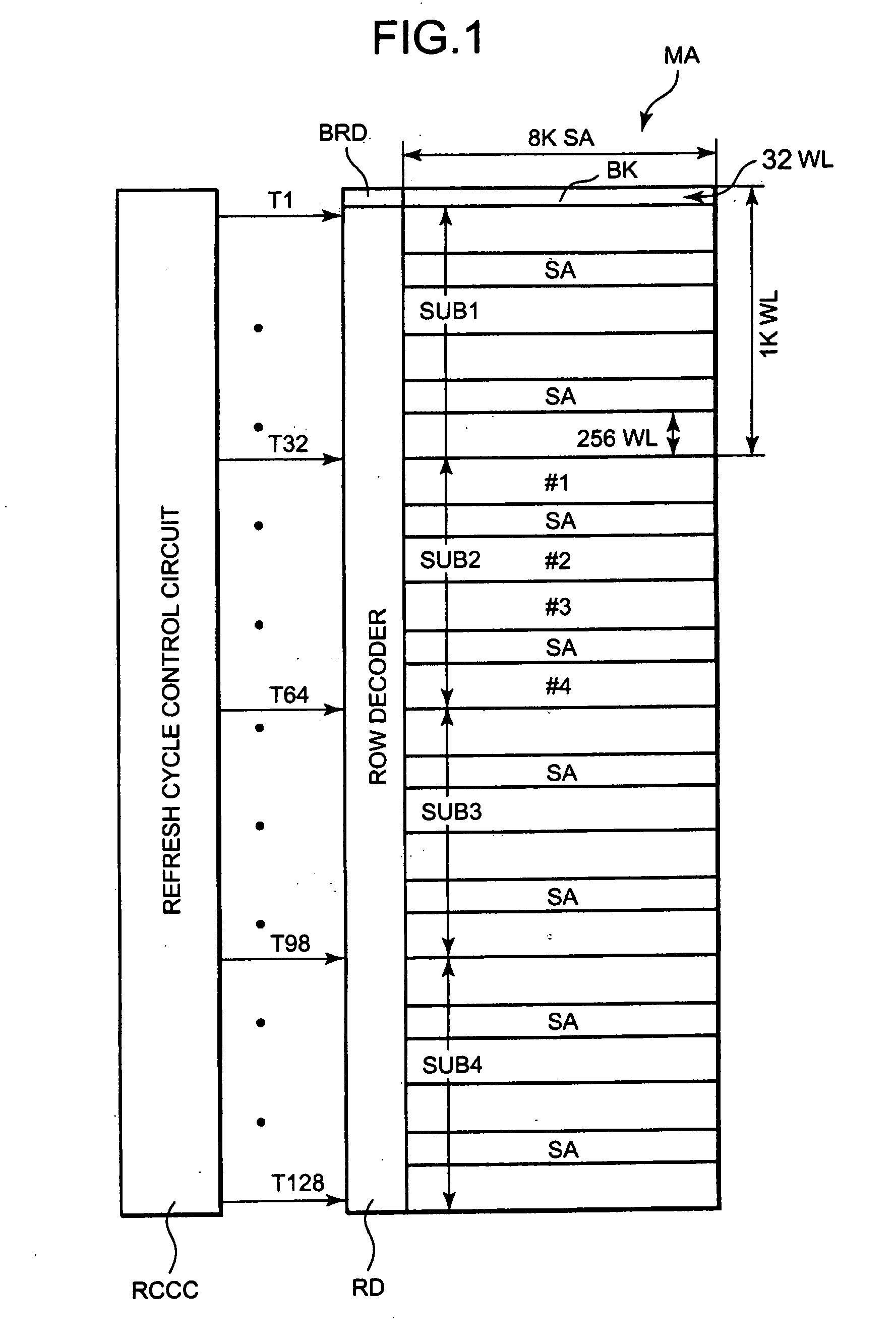
[0029] Referring to FIG. 1, a DRAM in accordance with the present invention has a 32-Mbit memory cell array MA, a row decoder RD, and a refresh cycle control circuit RCCC. The memory cell array MA is divided into four subarrays SUB 1 through SUB 4. Each of the subarrays SUB 1 through SUB 4 includes 8M (=8×220) memory cells (not shown) disposed in rows and columns, 1K (=210) word lines WL disposed in rows, 8K (=8×210) bit line pairs BL disposed in columns, and 8K sense amplifiers SA provided in association with the bit line pairs BL.
[0030] Each of the subarrays SUB 1 through SUB 4 is further divided into four regions #1 through #4, each of regions #1 through #4 including 256 word lines WL. The 4K sense amplifiers SA out of the 8K are disposed between regions #1 and #2 and another 4K sense amplifiers SA are disposed between regions #3 and #4. The entire memory cell array MA is further divided into 128 blocks BK, each block BK including 32 word lines WL.
[0031] To match the 128 blocks ...
second embodiment
[0067] Referring to FIG. 6, a DRAM according to the present invention has two memory cell arrays MA. Each memory cell array MA includes 32M memory cells (not shown) arranged in rows and columns, 16K word lines WL arranged in rows, and 2K bit line pairs BL arranged in columns. Each memory cell array MA has 32-Mbit memory capacity. The entire DRAM has a 64-Mbit memory capacity. Each memory cell array MA is divided into 64 subarrays SUB, each subarray SUB having 512-Kbit memory capacity.
[0068] Referring to FIG. 7, each subarray SUB has 512K memory cells (not shown), 256 word lines WL, and 2K bit line pairs BL. 2K sense amplifiers SA are individually connected to the 2K bit line pairs BL.
[0069] As shown in FIG. 7, a row-based peripheral circuit is disposed between the two, upper and lower, memory cell arrays MA shown in FIG. 6. The row-based peripheral circuit has a refresh cycle control circuit RCCC, two row decoders RD, two virtual word line decoder and word line drivers (hereinafter...
third embodiment
[0102] Referring to FIG. 11, the third embodiment has the fuse circuit FC0, but does not have the frequency divider FD0. Therefore, input predecode signal ZLI0 is always supplied directly to a row decoder RD as a predecode signal ZL0. A fuse signal FI0 output from a fuse circuit FC0 is supplied to all eight counters CTR1 to CTR8. When the fuse circuit FC0 is cut off and a fuse signal FI0 is switched to the H level, the counters CTR1 to CTR8 enable counter output signals Cout01 to Cout08 of LSB. When fuse circuits FC1 to FC8 are cut off and fuse signals FI1 to FI8 are switched to the H level, the counters CTR1 to CTR8 enable counter output signals Cout11 to Cout18 of MSB.
[0103] If a retention test result indicates that the shortest data retaining time of all blocks BK1 to BK8 is 128 ms or more, then the fuse circuit FC0 is cut off. If the shortest data retention time of, for example, block BK8 is 256 ms or more, then the fuse circuit FC8 is also cut off. In this case, the counter out...
PUM
 Abstract
Description
Claims
Application Information
 - R&D
- Intellectual Property
- Life Sciences
- Materials
- Tech Scout
- Unparalleled Data Quality
- Higher Quality Content
- 60% Fewer Hallucinations
Browse by: Latest US Patents, China's latest patents, Technical Efficacy Thesaurus, Application Domain, Technology Topic, Popular Technical Reports.
© 2025 PatSnap. All rights reserved.Legal|Privacy policy|Modern Slavery Act Transparency Statement|Sitemap|About US| Contact US: help@patsnap.com


