
Sliding bearing

a technology of sliding bearings and sliding surfaces, which is applied in the direction of rotary bearings, shafts and bearings, mechanical equipment, etc., can solve the problems of increasing the outer diameter of the bearing, affecting the rotational accuracy of the bearing, etc., to achieve excellent mechanical strength and durability, high dimensional accuracy and rotational accuracy, and rarely attacks

Inactive Publication Date: 2006-11-09
NTN CORP
View PDF14 Cites 26 Cited by
  • Summary
  • Abstract
  • Description
  • Claims
  • Application Information

AI Technical Summary

Benefits of technology

[0010] It is therefore an object of the present invention to provide a slide bearing which has high dimensional accuracy and rotational accuracy, rarely attacks a shaft member made of a soft metal and is excellent in mechanical strength and durability.

Problems solved by technology

When a shaft member to be supported is made of a soft metal material such as aluminum alloy material, a slide bearing made of a sintered metal may damage the sliding surface of the shaft member.
However, since resin materials typically have a larger linear expansion coefficient and higher water absorptivity than metal materials, when the use temperature range of the resin slide bearing is wide, a backlash between the bearing and the shaft member due to the shrinkage of the resin material during use at a low temperature and the outer diameter of the bearing may increase due to the expansion of the resin material during use at a high temperature.
Since the slide space between the shaft member and the slide bearing is changed by volume expansion caused by water absorption, it is difficult to use the slide bearing in fields that require rotational accuracy such as a field of office equipment.
When using in the devices in which the outer peripheral surface of a matrix comes into contact with a mating member to roll or slide, such as cam followers, the outer peripheral surface of the matrix tends to be damaged due to the insufficient strength of the matrix.

Method used


Image

  • Sliding bearing
  • Sliding bearing

Examples


example 1

[0048] A bearing matrix made of a φ8.5 mm×φ14 mm×5 mm sintered metal (Fe: 98.5 wt %-Cu: 1.5 wt %, average size of pores: 125 μm, average depth: 20 μm, proportion of depressions: 30%, linear expansion coefficient: 1.1×10⁻⁵ / ° C.) was prepared. This bearing matrix was placed in a mold for injection molding, and the following resin composition (slide material composition) was used to form a resin layer (slide layer) on the inner peripheral surface of the bearing matrix by the following method so as to manufacture a φ8 mm×φ14 mm×5 mm composite slide bearing (linear expansion coefficient of resin composition: 1.3×10⁻⁴ / ° C., thickness of resin layer: 250 μm). Tests were conducted by using the obtained composite slide bearing under the following conditions. The test results are shown in Table 1.

[0049] The Lubmer L5000 (polyethylene resin) manufactured by Mitsui Chemicals, Inc. was used as a base material. The KF96H-6000 (silicone oil) manufactured by Shin-Etsu Chemical Co., Ltd. was used a...

example 2

[0054] A φ8 mm×φ14 mm×t5 mm composite slide bearing was manufactured in the same manner as in Example 1 except that the thickness of the resin layer was changed to 500 μm. Tests were conducted by using the obtained composite slide bearing under the above conditions. The test results are shown in Table 1.

example 3

[0055] A φ8 mm×φ14 mm×t5 mm composite slide bearing was manufactured in the same manner as in Example 1 except that the thickness of the resin layer was changed to 770 μm. Tests were conducted by using the obtained composite slide bearing under the above conditions. The test results are shown in Table 1.


PUM


Abstract

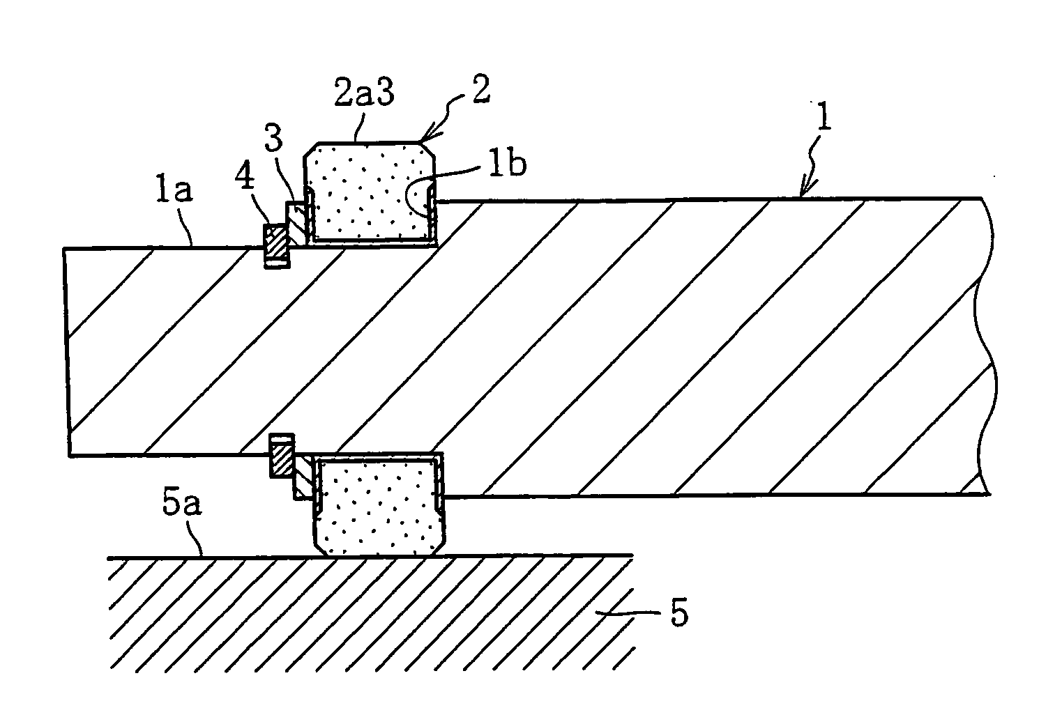
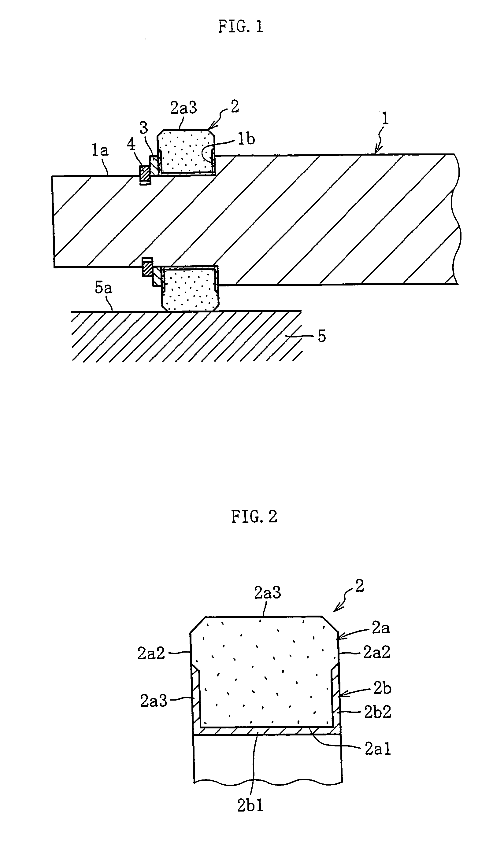
A cam follower includes a shaft member which is cantilevered at one end and a slide bearing fitted onto the outer periphery of the other end of the shaft member. The slide bearing is composed of a cylindrical matrix made of an Fe-based sintered metal material having an Fe content of 90 wt % or more and a slide layer formed from the inner peripheral surface to the both end faces of the matrix. The slide layer is made of a slide material composition having a base material such as polyethylene resin blended with a lubricant such as silicone oil and a globular porous silica impregnated with this lubricant.

Description

BACKGROUND OF THE INVENTION [0001] 1. Field of the Invention [0002] The present invention relates to a slide bearing having high accuracy, excellent sliding characteristics and strength characteristics. [0003] 2. Description of the Related Art [0004] Slide bearings made of Cu-based, Cu—Sn-based and Fe—Cu-based sintered metal materials have been known as slide bearings having high rotational accuracy. When the slide bearing is used after a bearing member made of a porous sintered metal material is impregnated with a lubricant (sintered oil-containing bearing), the lubricant can be continuously supplied to a sliding portion between the bearing and a shaft member. The bearing member made of a sintered metal material can improve in processing accuracy and is suitable for use in a portion requiring rotational accuracy. [0005] Resin slide bearings manufactured by mixing a solid lubricant such as PTFE, graphite or molybdenum disulfide, lubricating oil or wax with a resin material are also ...

Claims


Application Information

Patent Timeline
IPC IPC(8): F16C19/00F16C13/00F16C33/10F16C33/12F16C33/20
CPCF16C13/006F16C33/201F16C33/10F16C33/20F16C33/12F16H53/06
Inventor EGAMI, MASAKISHIMIZU, SEIJITANAKA, TOSHIHIKO
Owner NTN CORP
Learn More