

Abrasive tool and method of making the same
- Summary
- Abstract
- Description
- Claims
- Application Information
AI Technical Summary
Benefits of technology
Problems solved by technology
Method used
Image

Examples
Embodiment Construction
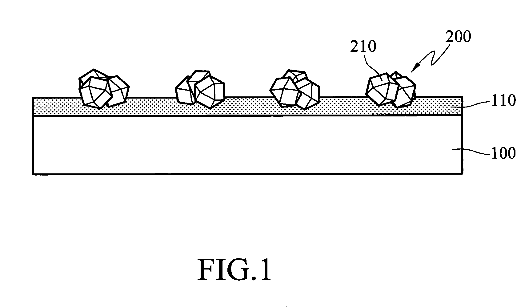
[0022] As described above, the disclosed abrasive tool and the method of making the same can increase the cutting rate of the abrasive tool and solve the problem of falling abrasive particles due to non-uniform pressures. The disclosed abrasive tool thus has a better polishing homogeneity and longer lifetime. The invention is particularly of use for making the polish pad conditioner / dresser in high-precision CMP. Therefore, we explain the structure of the polish pad conditioner / dresser that utilizes the invention and the method of making the same. We use diamond particles as the abrasive particles.
[0023] With reference to FIG. 1, it is seen that the polish pad conditioner / dresser in this embodiment includes: a substrate 100, a plurality of diamond particle groups 200, and a bonding layer 110. Each diamond particle group 200 consists of several diamond particles 210 grouped together. The diamond particle groups 200 are disposed in a regular pattern on the surface of the substrate 10...
PUM
| Property | Measurement | Unit |
|---|---|---|
| Length | aaaaa | aaaaa |
| Length | aaaaa | aaaaa |
| Length | aaaaa | aaaaa |
Abstract
Description
Claims
Application Information