Enhanced purge effect in gas conduit

a technology of gas conduit and purge effect, which is applied in the direction of process and machine control, container discharging methods, instruments, etc., can solve the problems of significant safety issues, etching and deposition processes of new semiconductor designs that often require extremely low levels of measurable contamination, etc., to achieve safety and reduce the consumption of purge gas, improve the purge efficiency, and achieve the effect of reducing the impurity level of the gas transfer apparatus

Inactive Publication Date: 2006-11-16
VERSUM MATERIALS US LLC
View PDF10 Cites 3 Cited by
  • Summary
  • Abstract
  • Description
  • Claims
  • Application Information

AI Technical Summary

Benefits of technology

[0020] an ability to improve the purge efficiency in long gas transfer conduits or pigtails to achieve safety and lower impurity levels in gas transfer apparatus, i.e., pigtail;
[0021] an ability to reduce purge gas consumption due to the use of fewer purge cycles; and,
[0022] an ability to obtain higher purity product gas through reduced contaminant level in the pigtail.

Problems solved by technology

The etching and deposition processes for new semiconductor designs often require extremely low levels of measurable contamination.
Use of reactive gases that may be pyrophoric and extremely toxic present significant safety issues when changing the gas supply.
As in change-out of gas sources for the electronic industry, other industries face similar issues.

Method used


Image

  • Enhanced purge effect in gas conduit
  • Enhanced purge effect in gas conduit
  • Enhanced purge effect in gas conduit

Examples


example 1

Evaluation of Surge Chamber in Reducing Purge Cycles and Impurity Level

[0043] A series of tests was carried out to determine the comparative effectiveness of surge chambers in terms of reducing the number of purge cycles to achieve preselected gaseous impurity levels in the pigtail conduit during change-out of an SF6 gas supply cylinder. The initial contamination level of SF6 impurities in the nitrogen purge gas was in excess of 100,000 ppb. The pigtail was pressurized with nitrogen to a pressure of 80 to 100 psig in a period of about 5 seconds and then evacuated to a pressure below atmospheric by applying vacuum. FIG. 5 is a plot of the results.

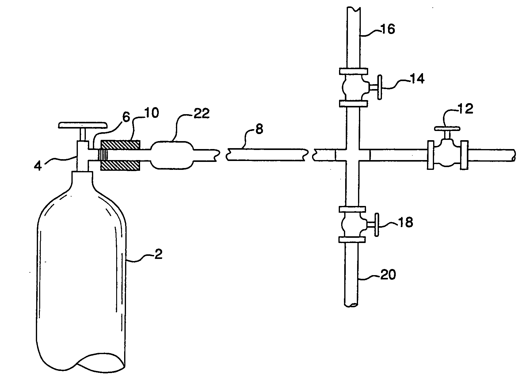
[0044] Run 1. Data Set 1, as represent in the graph, shows the results of a control purge procedure employing a prior art cross-purge procedure. It shows the impurity level of SF6 in a ¼ inch pigtail of 4 feet in length and having an external diameter of 0.25 inches, a wall thickness of 0.035 inches and thus and internal diameter of 0.180 ...

example 2

Evaluation of Surge Chamber in Moisture Removal From Pigtail

[0051] A series of tests was run to determine the effectiveness of a surge chamber in facilitating the removal of moisture from a ½ inch hard tube pigtail conduit employed in gas transfer apparatus. In this test procedure, each pigtail was saturated with moisture, moisture being selected because of the difficulty or removing moisture from pigtail conduits. 10 purge cycles were effected. More specifically, each pigtail was pressurized with nitrogen to a pressure of from 80 to 100 psig and then evacuated to a pressure of below atmospheric. After evacuation of the pigtail as the last step of the 10 cycle purge, a purge gas was passed through each pigtail and the moisture level in the purge gas plotted as a function of time. The area under the curve represents the amount of moisture remaining in the pigtail after 10 cycles of purging. It follows from the graph on FIG. 6, that the procedure having the minimum area under the cur...


PUM


Abstract

The present invention provides an improved gas transfer apparatus designed for enhanced purging of a pigtail and a process for effecting such purging. The improvement in the apparatus resides in an integrated system of components comprising: a surge chamber having a first end, a body and a second end, said first end in communication with the pigtail conduit, said body section of said surge chamber having a cross-section larger than the cross-section of said pigtail conduit and a second end in communication with said vessel containing said gas source; and, a purge gas source for delivery of a purge gas to said pigtail conduit whereby during an alternating cycle of pressurization of said pigtail with said purge gas and depressurization, optionally with application of vacuum within said pigtail conduit, impurities can be removed from within the pigtail conduit.

Description

BACKGROUND OF THE INVENTION [0001] It has become increasingly important in a number of various and diverse industries to have a source of high purity process gas. In the electronics industry, for example, reactive gases such as silane, arsine, diborane, phosphine, sulfur hexafluoride, hydrogen bromide, tungsten hexafluoride, and others are widely used in the semiconductor industry in the manufacture of integrated circuitry. The etching and deposition processes for new semiconductor designs often require extremely low levels of measurable contamination. Transfer lines have to be essentially free of contamination. Use of reactive gases that may be pyrophoric and extremely toxic present significant safety issues when changing the gas supply. [0002] Delivery of the process gases to a point of use is made through gas transfer conduits comprised of valves and connections. These conduits are commonly connected to a source such as gas cylinder, tube trailer, etc. and to a point of use deliv...

Claims


Application Information

Patent Timeline
Patent Type & Authority Applications(United States)
IPC IPC(8): G05D7/00
CPCF17C13/04F17C2221/05F17C2223/0123F17C2223/035Y02E60/321F17C2227/045F17C2250/0452F17C2260/044F17C2270/0518F17C2227/044Y10T137/0419Y10T137/4259Y02E60/32B08B9/027F17D3/08B08B9/04B08B9/032
Inventor BARKER, JOSEPH RAYMONDBOTELHO, ALEXANDRE DE ALMEIDACOLLINS, JOHN TIMOTHYTOTH, ANDREW JAMESPEARLSTEIN, RONALD MARTIN
Owner VERSUM MATERIALS US LLC
Why Eureka
Try Eureka