
Device for controlling light radiation

a technology of light radiation and control device, which is applied in the field of microscopy methods and arrangements, can solve the problems of poor efficiency of separation of excitation light from emitted light, poor optical resolution of arrangement, and poor efficiency of detection

Inactive Publication Date: 2006-11-16
CARL ZEISS MIKROLMAGING
View PDF9 Cites 11 Cited by
  • Summary
  • Abstract
  • Description
  • Claims
  • Application Information

AI Technical Summary

Benefits of technology

[0033] In addition, the suppression of the stray light is improved by at least one order of magnitude. Accordingly, fast switching between several excitation wavelengths or spectral detection wavelength ranges—so-called multi-tracking, as described in U.S. Pat. No. 6,462,345 B1,—can be realized in an especially simple manner.
[0035] Another advantage is that laser power fluctuations, caused by an unstable coupling into a glass fiber, can be prevented by automatic control, so that the output can be held constant at the site of the specimen.
[0036] Furthermore, the illumination distribution can be manipulated at the site of specimen interaction. This makes it possible to scan so-called regions of interest (ROI) in real time. In addition, the illumination methods known from wide field microscopy, such as oblique illumination, can be realized.
[0040] The quantity of the dye signatures, which may be used simultaneously, i.e., the quantity of the characteristics, for example, of cells that can be examined simultaneously, can be increased by means of the methods, according to the invention. When the spectral signatures of the individual dyes overlap extensively or are very close to one another, the detected wavelength range or numerical aperture must be limited, according to the prior art, for separate detection of the fluorescence signals of individual dyes. This reduces the sensitivity of detection, i.e., increases the noise of the detectors, because greater amplification must be used. This is avoided by the methods and arrangements of the invention.

Problems solved by technology

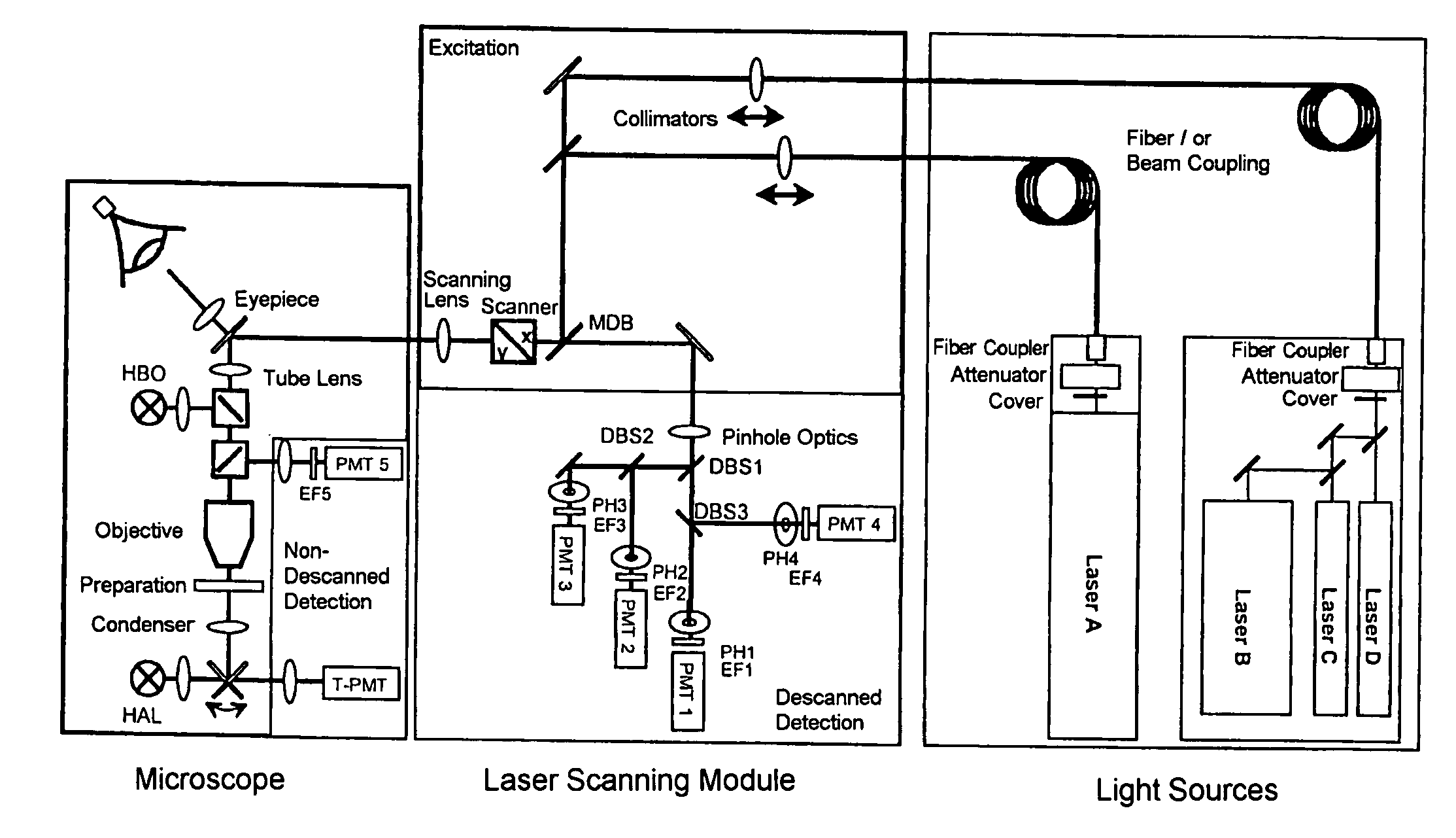
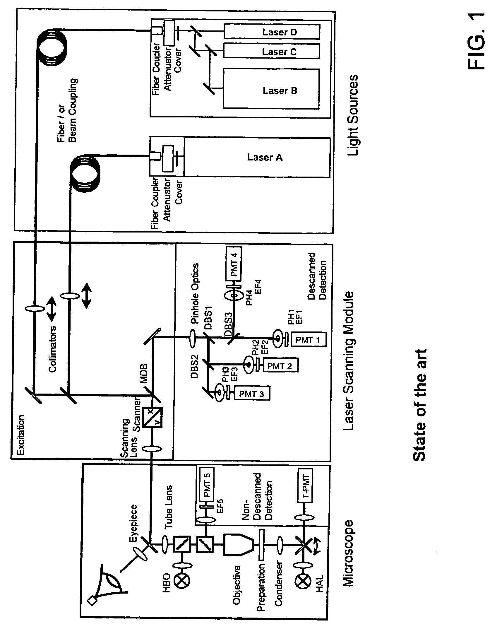
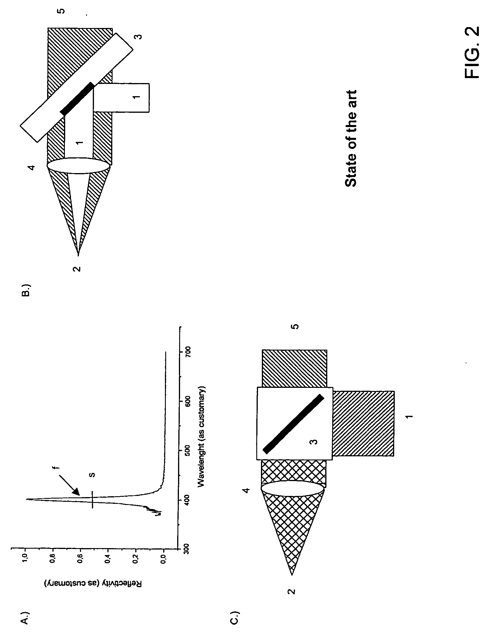
Hence, the use of dichroic beam splitters, according to the prior art, results in poor efficiency of the separation of the excitation light from the emitted light.
The drawback with the methods for dividing the numerical aperture, known from the prior art (e.g. EP 1353209), is that, on the one hand, the efficiency of detection and, on the other hand, the optical resolution of the arrangement is impaired due to the restriction of the aperture.
The drawback with all of the above described methods, according to the prior art, is that the separation of the excitation light from the light emitted by the specimen is carried out in a wavelength-dependent manner, i.e. not flexibly adjustable, or with a limited efficiency of typically 70% to 90%, depending on the required spectral characteristics and the quantity of illumination lines.
If this is not guaranteed, then the result is a reduction in the detection efficiency, particularly in the case of a confocal detection, and / or aliasing errors, because when different wavelengths are used, the excitation spots are not stacked.
The drawback with these arrangements lies in the need for a plurality of tunable optical components that have a negative impact on the overall transmission.
The drawback with this arrangement lies in the number of optical components for a spectral spatial splitting, by means of which the efficiency of the arrangement is reduced.
Depending on the specified spectral resolution, this array is costly with regard to the electronic wiring.
In addition, the speed is restricted when using a spatial light modulator and amounts to a few 10 ms.
Therefore, the action of the SLM in combination with the dispersive elements results in a phase delay and / or a change in the amplitude of the spectral components of the light source.
In addition, in contrast to the arrangements described below, the light source must be polarized linearly, because otherwise an energy loss occurs.

Method used


Image

  • Device for controlling light radiation
  • Device for controlling light radiation
  • Device for controlling light radiation

Examples


Embodiment Construction

[0057] A plurality of arrangements, with which the light radiation (hereinafter the detection light), which is excited in a specimen and / or which is backscattered by the specimen, can be separated especially efficiently from the excitation light. Thus, the arrangements are especially suitable for fast multi-tracking with a spectrally adjusted, flexible separation of the excitation radiation from the detection light. In the following context, light radiation emitted by the specimen is light that is radiated from the specimen preferably in a large solid angle. This light radiation is usually not polarized (unpolarized) and / or the magnitude of the polarization differs from the polarization of the excitation light. They are in particular fluorescent light, luminescent light and backscattered light that are excited in the specimen.

1. Functional Principle of the Arrangement for Separating the Excitation Light from the Detection Light in a Variable Manner

[0058]FIGS. 6A and 6B depict an ...


PUM

PropertyMeasurementUnit
edge lengthaaaaaaaaaa
wavelengthaaaaaaaaaa
angleaaaaaaaaaa

Abstract

Device for controlling light radiation, which is excited in a specimen and / or which is backscattered and / or reflected and which contains one or more wavelengths, at a plurality of light outlets, wherein a separation of the light radiation into differently polarized components is carried out; and the components of the excitation radiation and / or detection radiation are affected in their polarization by means of a preferably birefringent, preferably acousto-optic or electro-optic medium, which changes the ordinary and extraordinary refractive index.

Description

BACKGROUND OF THE INVENTION [0001] 1. Field of the Invention [0002] The invention relates to a method and arrangements in microscopy, in particular fluorescence microscopy, laser scanning microscopy, fluorescence correlation spectroscopy and near-field scanning microscopy, for examining predominantly biological specimens, preparations and related components. This includes methods for screening active ingredients based on fluorescence detection (high throughput screening) as well as methods of flow cytometry. Therefore, simultaneous examinations of specimens with multiple fluorophores in real time by means of simultaneous illumination of the specimen at multiple sampling points are possible with overlapping fluorescence spectra even in three dimensional structures of thick specimens. [0003] 2. Related Art [0004] A typical field of application of light microscopy for examining biological preparations is fluorescence microscopy (literature: Pawley. Handbook of Biological Confocal Micro...

Claims


Application Information

Patent Timeline
Patent Type & Authority Applications(United States)
IPC IPC(8): G02F1/33
CPCG01J3/0224G01J3/1256G01J3/4406G01J3/447G02B27/283G01N21/6458G02B21/002G02B21/0068G01N21/6445
Inventor WOLLESCHENSKY, RALF
Owner CARL ZEISS MIKROLMAGING
Learn More