Transparent conductive film and coating composition therefor

a technology of transparent conductive film and coating composition, which is applied in the direction of conductive layers on insulating supports, transportation and packaging, chemistry apparatus and processes, etc., can solve the problems of limited range of applicable substrate materials, difficult to uniformly disperse the fibers throughout the thermoplastic resin matrix, and difficulty in controlling electrical characteristics

Inactive Publication Date: 2006-11-23
MITSUI & CO LTD +1
View PDF6 Cites 102 Cited by
  • Summary
  • Abstract
  • Description
  • Claims
  • Application Information

AI Technical Summary

Problems solved by technology

However, there are several restrictions on these materials, such as difficulty in controlling their electrical characteristics, and limited range of applicable substrate materials.
In the transparent conductive resin boards shown in JP-2001-62952A, JP-2004-195993A and JP-2004-230690A, however, it is difficult to disperse the fibers uniformly throughout the thermoplastic resin matrix since the long carbon fibers or carbon nanotube

Method used


Image

  • Transparent conductive film and coating composition therefor
  • Transparent conductive film and coating composition therefor
  • Transparent conductive film and coating composition therefor

Examples


synthetic example 1

[0086] Carbon fibrous structures were synthesized using toluene as a raw material in a CVD process.

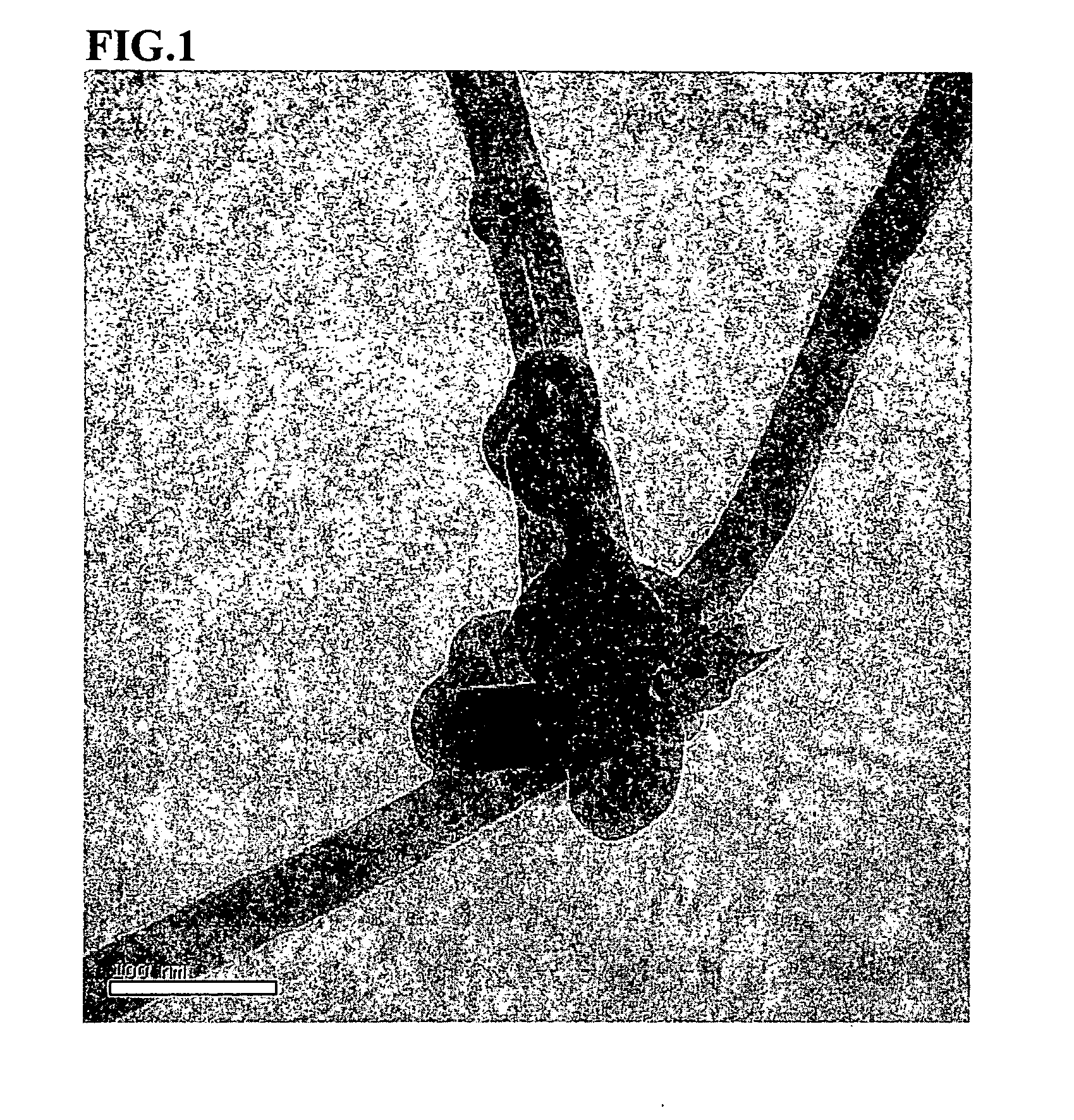
[0087] The synthesis was carried out in the presence of a mixture of ferrocene and thiophene as a catalyst, and in the reducing atmosphere of hydrogen gas. The toluene and the catalyst were heated to 380° C. along with the hydrogen gas. The heated mixture was then supplied to a generation furnace and subjected to thermal decomposition at 1250° C. in order to obtain carbon fibrous structures (the first intermediate). The synthesized first intermediate was baked at 900° C. in nitrogen gas in order to remove hydrocarbons, such as tar, to produce a second intermediate. The R value of the second intermediate, as measured by Raman spectroscopic analysis, was found to be 0.98. A sample for electron microscopy was prepared by dispersing the first intermediate into toluene. FIG. 1 shows a TEM photo of the sample.

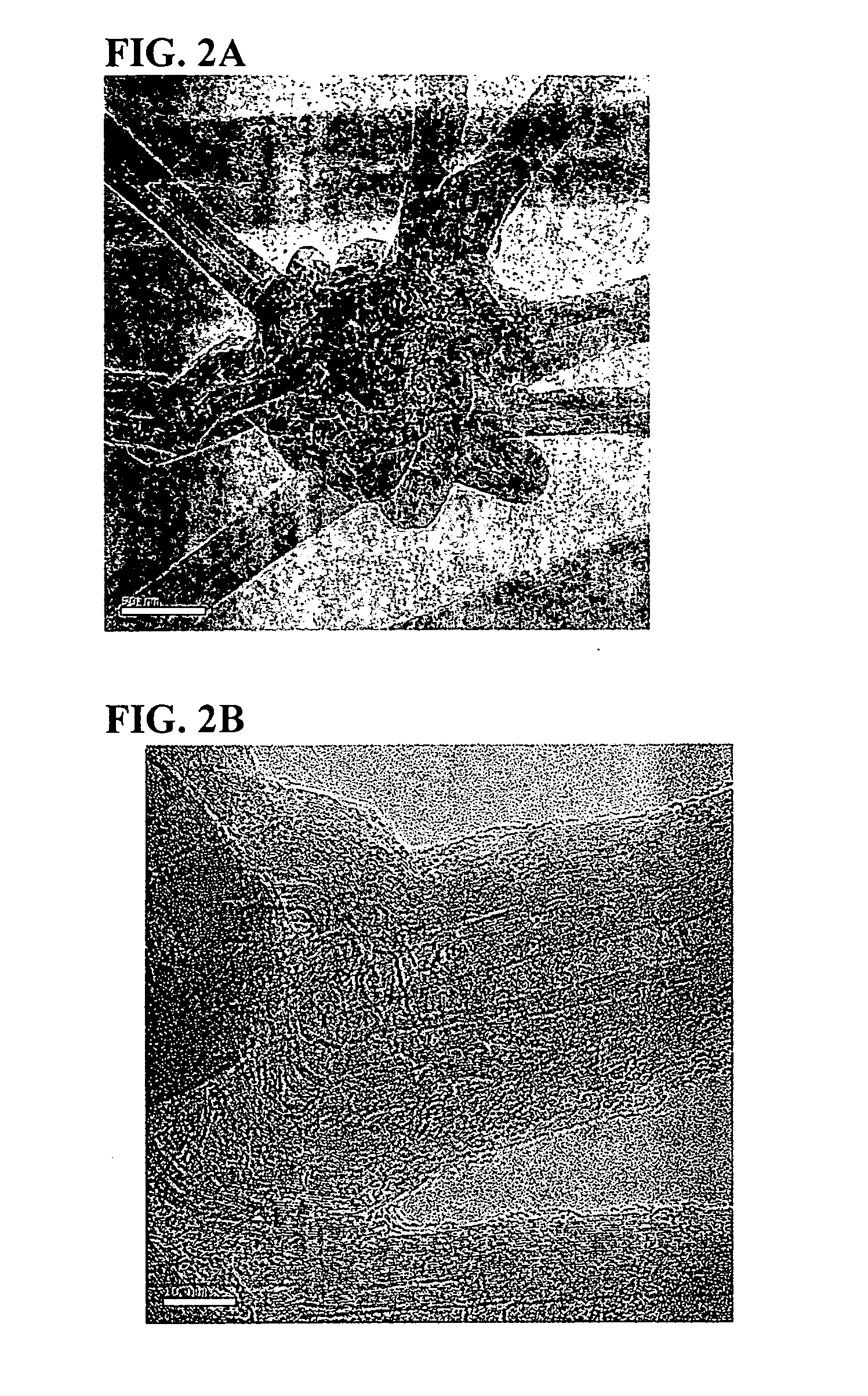
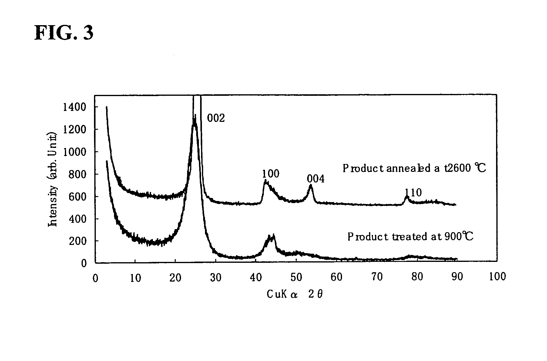
[0088] The second intermediate was further subjected to a high temperature heatin...

examples 1-9

[0091] The carbon fibrous structures obtained in Synthetic Example 1 was added to 100 parts by weight of polyurethane resin solution (non-volatile matter: 20%) at ratios shown in Table 1. The resultant mixture was pulverized and dispersed by using a bead mill (DYNO-MILL, manufactured by SHINMARU ENTERPRISES CORPORATION) with zirconium beads (0.05 mm, 0.5 mm, 1.0 mm, or 1.5 mm in diameter) at a peripheral speed of 10 m / sec, a bead filling rate of 80% by volume, and a processing time of 2 hrs. As a result, a coating composition comprising the carbon fibrous structures dispersed therein was prepared.

[0092] The liquid resinous composition obtained above was coated on a glass plate to obtain a hardened film of a prescribed thickness shown in Table 1. The hardened film was tested for coating ability, total light transmittance, and surface resistivity. The results obtained are shown in Table 1.

[0093] Furthermore, the dispersion condition of the carbon fibrous structures in the hardened c...

reference examples 1-6

[0094] To prepare the coating compositions of Reference Examples 1-6, the same procedure in Examples 1-9 was repeated except that the dispersion method and its condition were changed as shown in Table 1. Then, the same tests for coating ability, total light transmittance, and surface resistivity as in Examples 1-9 were performed. The results obtained are shown in Table 1.

Controls 1-4

[0095] Multilayered carbon nanotubes (manufactured by Tsinghua Nafine, 10-20 nm in outer diameter, several μm to several tens μm in length) were added to 100 parts by weight of a polyurethane resin solution (non-volatile matter: 20%) at ratios shown in Table 1. The resultant mixture was pulverized and dispersed by using a bead mill (DYNO-MILL, manufactured by SHINMARU ENTERPRISES CORPORATION) with zirconium beads (0.05 mm, or 1.5 mm in diameter) at a peripheral speed of 10 m / sec, a bead filling rate of 80% by volume, and a processing time of 2 hrs. As a result, a coating composition comprising the carb...


PUM

PropertyMeasurementUnit
Percent by massaaaaaaaaaa
Thicknessaaaaaaaaaa

Abstract

The disclosed is a transparent conductive film that includes a matrix and carbon fibrous structures added to the matrix, wherein the carbon fibrous structures comprise carbon fibers, each having an outside diameter of 15-100 nm, and wherein the carbon fibrous structures each comprise a granular part at which two or more carbon fibers are bound to each other, and wherein the granular part is concurrently produced in a growth process for the carbon fibers. When the transparent conductive film is formed at a thickness of 0.1-5 μm on a glass substrate, it shows a surface resistivity of not more than 1.0×10¹²Ω/□, and a total light transmittance of not less than 30%. A coating composition for the conductive transparent film is prepared by using a media mill equipped with beads having an average diameter of 0.05-1.5 mm to disperse the carbon fibrous structures into the liquid resinous composition.

Description

CROSS REFERNCE TO RELATED APPLICATIONS [0001] This claims priority of Japanese Patent Application No. 2005-132691, filed on Apr. 28, 2005, the disclosure of which, including the specification, claims, drawings and summary, is incorporated herein by reference in its entirety. BACKGROUND OF THE INVENTION [0002] 1. Technical Field [0003] This invention relates to a transparent conductive film and a coating composition for the transparent conductive film. More particularly, this invention relates to a transparent conductive film that has a good transparency and a high conductivity, as well as to a coating composition for forming the transparent conductive film. Background Art [0004] Transparent conductive films have been utilized as electrode materials for liquid crystal display devices, organic electroluminescent (EL) devices, and various other electronic devices. They have also been used for the purpose of removing static electricity from transparent members in order to prevent sticki...

Claims


Application Information

Patent Timeline
IPC IPC(8): D04H1/00
CPCB82Y30/00B82Y40/00C01B31/0253C01B2202/06H01B1/24C01B2202/36C08J5/042C08K7/06C01B2202/34C01B32/168Y10T428/249924H01B5/14
Inventor HANDA, KOICHISUBIANTORO,TSUKADA, TAKAYUKISHAN, JIAYIASHIDA, TADASHINATORI, TOSHIKI
Owner MITSUI & CO LTD
Why Eureka
Try Eureka