Concentrator solar photovoltaic array with compact tailored imaging power units

a solar photovoltaic array and compact technology, applied in the direction of instruments, light radiation electric generators, lighting and heating apparatus, etc., can solve the problems of not being able to capture the above preferences and others, and no single design has achieved the above, etc., to achieve convenient cooling, reduce dimensions and costs, and reduce the effect of relative ease of assembly

Inactive Publication Date: 2006-11-30
H2GO
View PDF49 Cites 156 Cited by
  • Summary
  • Abstract
  • Description
  • Claims
  • Application Information

AI Technical Summary

Benefits of technology

[0005] Many embodiments of the presently disclosed technology provide for a power unit design that is axially compact (such as less than about 20 cm in some embodiments). Reduced dimensions and cost as well as relative ease of assembly are some of the many advantages afforded by select embodiments of the presently disclosed technology.
[0006] Yet another advantage in accordance with certain embodiments of the present invention concerns the completely passive cooling options offered in each power unit design. The concentrator assembly of each power unit is positioned at the back of each power unit, thus providing it in a location that can be readily cooled. Concentrator units may include a heat spreading element consisting of a relatively large base plate that functions as a simple heat spreader and serves to provide certain mechanical functionality for the assembly as well to radiate heat emitted by the concentrator assembly's solar cell. In some embodiments, an additional heat sink element may also be provided adjacent to each solar cell for further passive cooling.
[0007] A still further advantage of so

Problems solved by technology

Although many PV assemblies and related solar systems have been developed, no single desig

Method used


Image

  • Concentrator solar photovoltaic array with compact tailored imaging power units
  • Concentrator solar photovoltaic array with compact tailored imaging power units
  • Concentrator solar photovoltaic array with compact tailored imaging power units

Examples


first embodiment

[0041] The perimeter of each primary mirror 22 may be formed in a variety of different fashions, and select exemplary embodiments depicting several options will now be presented and discussed with reference to FIGS. 3A-5B, respectively. In a first embodiment, such as illustrated in the plan view of FIG. 4A and the perspective view of FIG. 4B, the perimeter of primary mirror 22b is formed in a generally circular configuration. With a generally circular configuration, the entire perimeter of the primary mirror 22b may be substantially coplanar with the perimeter of secondary mirror 24 and both circular perimeters may be in contact with and / or adhered to the inner surface of front window 26. In one particular embodiment of the disclosed technology, the perimeter of generally circular primary mirror 22b is formed with an exemplary diameter 60 of about 280 mm, the perimeter of generally circular secondary mirror 24 is formed with an exemplary diameter 62 of about 50 mm, and the depth 64 ...

second embodiment

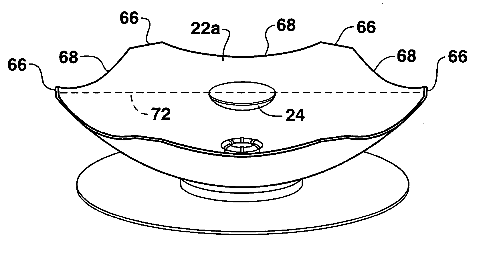
[0042] A second embodiment depicting an exemplary shape for primary mirror 22 is provided in the plan view of FIG. 3A and perspective view of FIG. 3B, in which the perimeter of primary mirror 22a is formed in a near-hexagonal fashion. The perimeter of primary mirror 22a is defined by six full sections 66 and six truncated sections 68. Full sections 66 are substantially coplanar with one another such that they may be provided in contact with and / or adhered to the inner surface of front window 26. The distance 70 measured in a straight line from the edge of adjacent full sections 66 is about 132 mm in one exemplary embodiment of the present technology. The distance 72 measured across the diameter of the perimeter of primary mirror 22a may be about 300 mm in one exemplary embodiment. Each truncated section 68 of the perimeter of primary mirror 22a is formed to define a generally arched segment that extends away from front window 26. Each truncated section 68 exists in a respective vert...

third embodiment

[0043] A third embodiment depicting an exemplary shape for primary mirror 22 is provided in the plan view of FIG. 5A and the perspective view of FIG. 5B, in which the perimeter of primary mirror 22c is formed in a near-square configuration. The perimeter of primary mirror 22c is defined by four full sections 74 and four truncated sections 76. Full sections 74 are substantially coplanar with one another such that they may be provided in contact with and / or adhered to the inner surface of front window 26, while each truncated section 76 exists in a respective plane that is substantially perpendicular to front window 26 when the primary mirror is adjacent thereto. The distance 80 measured across the perimeter of primary mirror 22c may be about 250 mm in one exemplary embodiment.

[0044] It should be appreciated in some embodiments of the disclosed technology that the respective perimeters (or portions thereof) of the primary and secondary mirrors may not be precisely arranged in a coplan...


PUM


Abstract

Solar panels and assembled arrays thereof include a collection of relatively compact, high-capacity power units. Optical components of each power unit include a front window or surface glazing, a primary mirror, secondary mirror and receiver assembly. Primary and secondary mirrors are defined by respective perimeters, at least a portion of which may be substantially coplanar and in contact with the front window. Some primary mirrors are configured with a perimeter of alternating full and truncated sections, and are curved to a base portion forming a pilot hole therein. Receiver assembly mechanical components include an alignment tube for mating with the primary mirror's pilot hole and for housing a photovoltaic solar cell. A base plate provided adjacent to the alignment tube serves to radiate heat emitted by the solar cell, and in some embodiments an additional heat sink provides further passive cooling. A tapered optical rod also provided within the receiver assembly directs received sunlight to the solar cell where electrical current is generated.

Description

BACKGROUND OF THE INVENTION [0001] It is generally appreciated that one of many known technologies for generating electrical power involves the harvesting of solar radiation and its conversion into direct current (DC) electricity. Solar power generation has already proven to be a very effective and “environmentally friendly” energy option, and further advances related to this technology continue to increase the appeal of such power generation systems. [0002] A particular type of module utilized in conventional solar systems employs photovoltaics or “PV” cells, in which an electrical field is created at the P-N junction of a silicon wafer or other semiconductive material. PV cells may be configured into modules and arrays that convert impinging solar radiation into electrical power, and can be employed in a wide variety of applications, such as charging batteries, operating motors, powering electrical loads, etc. As a power generation and distribution solution, PV modules can provide...

Claims


Application Information

Patent Timeline
IPC IPC(8): H02N6/00
CPCF24J2/067F24J2/18H01L31/052Y02E10/40H01L31/0547G02B19/0042G02B19/0028G02B19/0033Y02E10/52F24S23/79F24S23/12
Inventor HORNE, STEPHEN JOHNCONLEY, GARY D.
Owner H2GO
Why Eureka
Try Eureka