Motor drive inverter that includes III-nitride based power semiconductor devices

a technology of inverter and semiconductor device, applied in the direction of motor/generator/converter stopper, dynamo-electric converter control, dynamo-electric gear control, etc., can solve the problem of limited emi noise caused by sharp voltage change, no stored charge available to boost switching loss, etc. problem, to achieve the effect of reducing power loss, overcoming turn-on switching loss and emi noise, and reducing power loss

Active Publication Date: 2006-11-30
INFINEON TECH AMERICAS CORP
View PDF8 Cites 23 Cited by
  • Summary
  • Abstract
  • Description
  • Claims
  • Application Information

AI Technical Summary

Benefits of technology

[0015] According to an embodiment of the invention, each bi-directional switching device includes two independent gate leads that control the forward and reverse conducting paths of the switch. According to an embodiment of the invention, the two gate leads of each switching device are connected to respective control leads of the controller. In this way, the controller may configure any given switch to conduct current in the forward direction or the reverse direction. In operation, the controller may be configured so as to produce control signals on the control leads to configure the forward and reverse conducting paths of each switch to generate three, phase-displaced AC power signals that energize the motor windings.
[0016] Significantly, the bi-directional switching devices of the inverter of the present invention overcome the limitations caused by the diodes of prior motor drive inverters. Specifically, the bidirectional switching devices have lower power dissipation as compared to the diodes, thereby reducing power loss. The bidirectional switching devices also overcome the turn-on switching losses and EMI noise caused by the diodes discharging the Qrr charge as the diodes are turned “off”. Specifically, because each bi-directional switch of the present invention has two gates, the controller is able to turn the forward conducting path of a switch “on” and the reverse conducting path of the switch “off”, rather than having the reverse conducting path forced “off”, as with a diode. As a result, there is no stored charge available to boost switching loss and to produce radiated and conducted EMI noise. Accordingly, the bi-directional switches of the inverter of the present invention result in a motor drive that has reduced power loss, improved thermal performance, higher power density, lower cost, and reduced EMI noise.
[0017] The motor drive of the present invention also addresses the radiated and conducted EMI noise caused by the sharp dV / dt and fast di / dt that results as the high side switch of a power stage transitions from an “off” to an “on” configuration and the low side switch moves from a reverse conducting state to a non-conducting state. Specifically, the EMI noise caused by the sharp voltage change may be limited by configuring the gate resistance of the gates of the bi-directional switches. As for the noise caused by the fast change in current, according to an embodiment of the invention, the controller may synchronize the reconfiguration of the high side and low side bi-directional switches such that the reverse conducting path of the low side switch is turned “off” before the forward conducting path of the high side switch is turned “on”. In general, this technique is comparable to the synchronous rectification technique used in switch mode power supplies. Accordingly, the inverter of the present invention allows for the transitional noise to be controlled while also not incurring a power loss, unlike prior systems.

Problems solved by technology

As a result, there is no stored charge available to boost switching loss and to produce radiated and conducted EMI noise.
Specifically, the EMI noise caused by the sharp voltage change may be limited by configuring the gate resistance of the gates of the bi-directional switches.

Method used


Image

  • Motor drive inverter that includes III-nitride based power semiconductor devices
  • Motor drive inverter that includes III-nitride based power semiconductor devices
  • Motor drive inverter that includes III-nitride based power semiconductor devices

Examples


Embodiment Construction

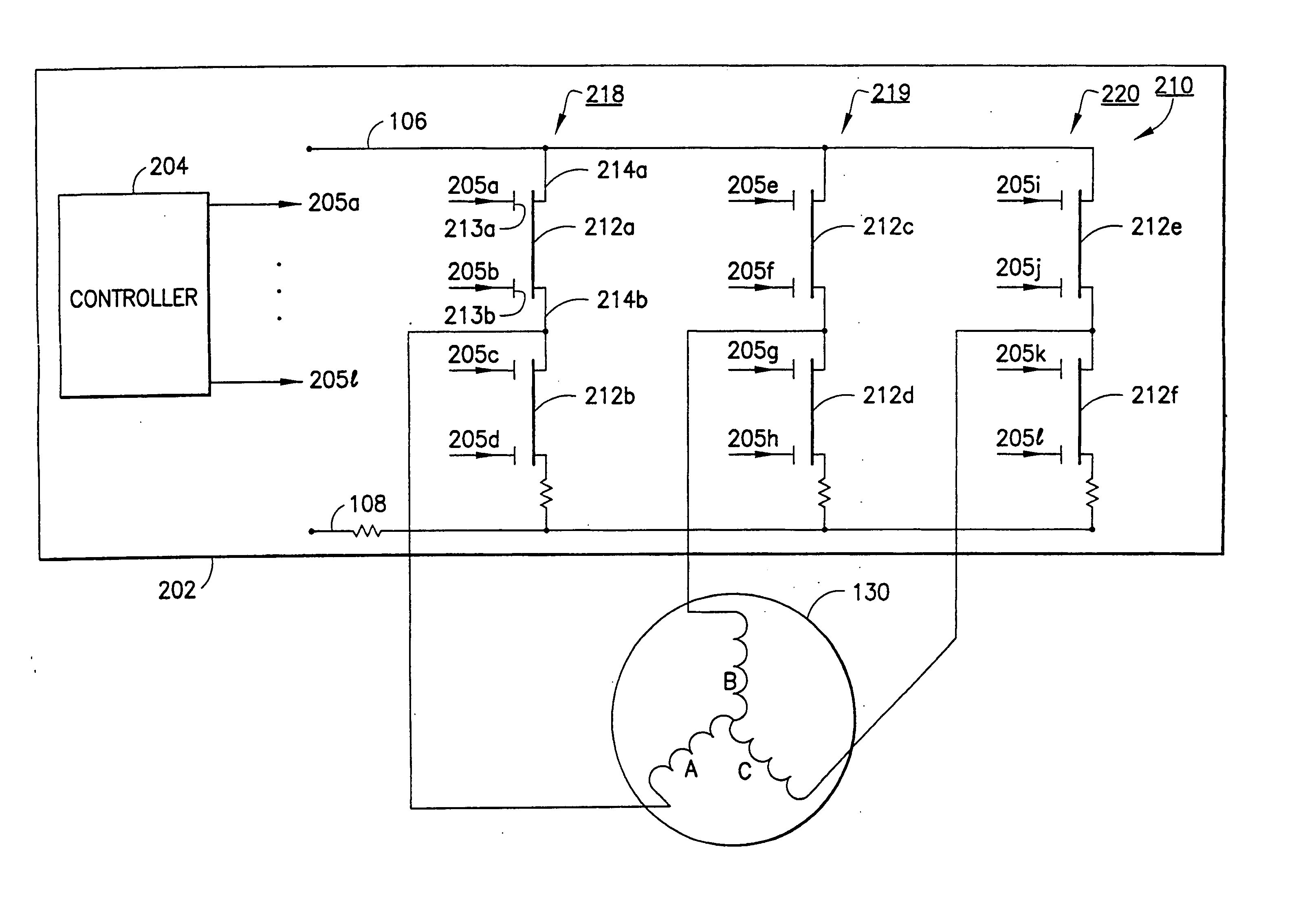
[0022] Referring to FIG. 3, there is shown a schematic of a motor drive 202 for a three phase AC electric motor 130 according to an embodiment of the invention. As described above, motor 130 includes three windings A, B, and C and may be an induction motor or a BLDC motor, for example, and in particular, may be a servo motor, for example. Motor drive 202 includes a controller 204 and an inverter 210. As shown in FIG. 3, inverter 210 is a three phase inverter that includes three power stages 218, 219, and 220 that are connected in parallel across DC voltage bus 106 and ground lead 108. Each power stage is connected to a respective one of the three windings A, B, and C of motor 130. According to an embodiment of the invention, controller 204 includes twelve controls leads, labeled 205a-205L, which leads are connected to respective ones of power stages 218-220. In operation, controller 204 generates control signals on the control leads, which signals configure inverter 210 to produce t...


PUM


Abstract

An inverter for driving a motor includes one or more power stages for producing one or more power signals for energizing the motor, each power stage including first and second III-nitride based bi-directional switching devices connected in series between a DC voltage bus and ground.

Description

RELATED APPLICATIONS [0001] This application is based on and claims priority to U.S. Provisional Application No. 60 / 668,757, filed on Apr. 5, 2005, by Mario Battello and Stephen Oliver, entitled, “INVERTER AMPLIFIER FOR MOTOR DRIVE APPLICATION USING BI-DIRECTIONAL SWITCH,” the contents of which are herein incorporated by reference.BACKGROUND OF THE INVENTION [0002] 1. Field of the Invention [0003] This invention relates to inverters for motor drives and more specifically, relates to inverters that include III-nitride based power semiconductor devices. [0004] 2. Description of the Art [0005] Referring to FIG. 1, there is shown a schematic of a motor drive 102 for a three phase AC electric motor 130 according to the prior art. Motor 130 may be an induction motor or a brushless DC (BLDC) motor, for example. Motor 130 includes a stator having a three winding system A, B, and C and further includes a rotor having a shaft, the rotor / shaft being disposed within the stator (note that FIG. 1...

Claims


Application Information

Patent Timeline
Patent Type & Authority Applications(United States)
IPC IPC(8): H02P27/04
CPCH02P6/085H02M7/003
Inventor BATTELLO, MARIOOLIVER, STEPHEN
Owner INFINEON TECH AMERICAS CORP
Why Eureka
Try Eureka