Method and program for labeling multi material data

a multi-material data and labeling technology, applied in the field of multi-material data labeling method and program, can solve the problems of data loss, inability to apply the region growing (expanding) method to a case, and time-consuming, so as to improve processing speed, shorten processing time, and facilitate implementation into the computer

Inactive Publication Date: 2006-11-30
RIKEN
View PDF3 Cites 13 Cited by
  • Summary
  • Abstract
  • Description
  • Claims
  • Application Information

AI Technical Summary

Benefits of technology

[0023] The present invention was made in order to solve the above problems. It is an object of the present invention to provide an labeling method and program, which is so robust against any defect in boundary information that it can identify the boundary informat

Problems solved by technology

However, the region growing (expanding) method cannot be applied to a case where rays come into accidental contact with a boundary, because this expansion has a repeated root so that two intersecting points will become one.
It cannot also be applied to a case where there is a defect in boundary information (when data such as CAD data are read from different software, the data may be lost due to differences in representation or numerical value errors).
However, since the processing is performed over the entire region, it takes time.
Further, when there is a defect in surface information, the determination cannot be made properly.
However, when a quantized image is formed from defective boundary information, for example when the surface is not a closed surface, proper determination cannot be made.
332) can be used, but the efficiency of this method is low.
However, in the Curless method, since it is necessary to perform distance field calculations for all cells, this method has demerits in terms of data amount

Method used


Image

  • Method and program for labeling multi material data
  • Method and program for labeling multi material data
  • Method and program for labeling multi material data

Examples


embodiment

[0112] The following describes a specific example of the preferred embodiment of the present invention.

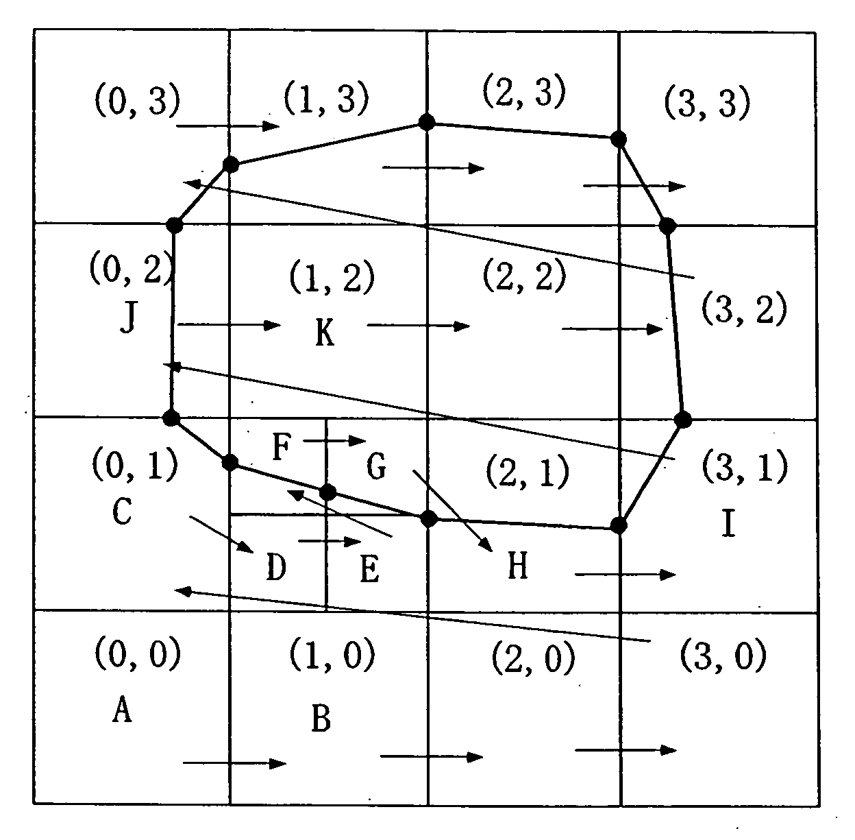
[0113]FIG. 3 shows the types of cells and the positions of cutting points. In FIG. 3, each square or grid represents a cell. The large cells and small cells are the representation of a two-level hierarchy. Further, black circles are cutting points, and line segments connecting the black circles indicate an inner cell face, that is, boundary data.

(Type of Cell)

[0114] The cells are classified into a non-boundary cell type, a boundary cell type, and a transit cell type. The term “non-boundary cell” refers to a cell without cutting point. The term “boundary cell” refers to a cell with one or more cutting points. The term “transit cell” refers to a cell larger in hierarchy than the other neighboring cells and having a cutting point on its boundary with the lower-level cells.

[0115] The boundary cell has a cutting point only on a cell edge or vertex. In many cases, the boundary cell ...


PUM


Abstract

The present invention includes an external data acquisition step (S1), an external data input step (A), a cell division step (B), a cell classification step (C), a space classification step (D), a simulation step (S3), and an output step (S4). The cell classification step (C) includes a step of further classifying each of the boundary cells (13a) into a first type cell and a second type cell. The first type cell has a cutting point at which an edge line or vertex is cut by the boundary data. The second type cell has a cutting point that lies on a boundary with another cell of different hierarchy, and is larger than the another cell. The cell classification step (C) further includes a step of assigning a material number to each cell vertex.

Description

BACKGROUND OF THE INVENTION [0001] 1. Technical Field of the Invention [0002] The present invention relates to a multi-material data labeling method and program for determining the insides / outsides of two-dimensional or three-dimensional boundary surfaces. [0003] 2. Description of Related Art [0004] In the field of technology research and development, CAD (Computer Aided Design), CAM (Computer Aided Manufacturing), CAE (Computer Aided Engineering), CAT (Computer Aided Testing), and the like are used as simulation means for designing, machining, analyzing, and testing, respectively. [0005] In addition, C-Simulation (Corporative Simulation) as continuous simulation, A-CAM (Advanced CAM) which also considers a machining process, and D-fabrication (Deterministic fabrication) providing ultimate accuracy are becoming widespread. [0006] In the conventional simulation means mentioned above, the boundary surfaces of an object are important. For example, it is common practice to represent the...

Claims


Application Information

Patent Timeline
IPC IPC(8): G06T15/00G06F17/50
CPCG06F17/5018G06F30/23
Inventor KATO, MASAYAKASE, KIWAMUYAMADA, TOMONORI
Owner RIKEN
Why Eureka
Try Eureka